 EN


How High Frequency CCA Wire Behaves Under Different Signal Frequency Ranges for RF Projects
For an RF project, high frequency CCA wire is not judged by a single universal cutoff. Copper-clad aluminum (CCA) combines a copper outer layer with an aluminum core, so its behavior changes as RF current moves closer to the conductor surface. The useful question is not simply whether CCA is “good” or “bad” at high frequency. It is whether the copper layer, conductor geometry, dielectric system, shielding, and finished-cable test results match the operating band and loss budget.
From a conductor-material selection perspective, the first step is to define the RF band, cable construction, run length, allowable insertion loss, impedance tolerance, connector interfaces, and test method. That prevents a common mistake: treating the name high frequency CCA wire as a complete electrical specification. A wire can have the right material family yet be unsuitable for a particular cable design if copper thickness or dimensional control is not aligned with the application.
Why frequency changes the picture
At low frequencies, current can use more of a conductor’s cross-section. Aluminum’s conductivity is lower than copper’s, so the aluminum core matters more to the resistance of a CCA conductor in that region. As frequency rises, skin effect concentrates alternating current nearer the outer surface. In a properly designed high frequency CCA wire, the copper cladding can carry a larger share of the RF current because the active current path becomes shallower.
Skin depth is a helpful engineering concept, not a substitute for qualification. For nonmagnetic conductive materials, it decreases approximately with the inverse square root of frequency. That means a change from 10 MHz to 100 MHz does not simply multiply behavior by ten; it reduces the depth of strongest current penetration by about the square root of ten. Copper thickness therefore has to be compared with skin depth across the intended band, especially near the low end where skin depth is larger.
It is also important to separate conductor behavior from cable behavior. A finished RF cable’s attenuation depends on conductor loss, dielectric loss, shield construction, dimensions, surface condition, connectors, bend condition, and installation environment. As frequency rises, total attenuation commonly rises too, but no reliable loss number can be assigned to high frequency CCA wire without a defined cable design and a relevant test.
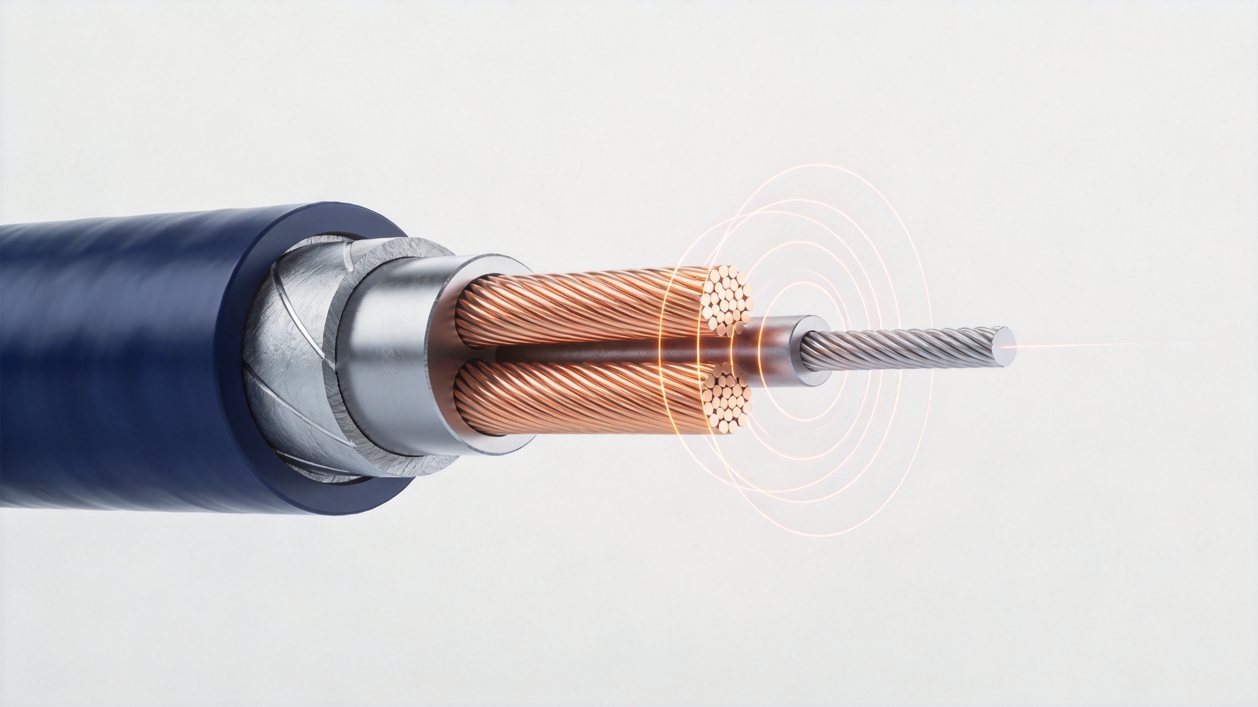
Behavior by practical signal-frequency range
Lower RF and transition bands: verify bulk resistance and copper coverage
In lower RF or transition-band work, the current penetrates more deeply than it does at microwave frequencies. The aluminum core may contribute more to the electrical result, so DC resistance and low-frequency AC resistance deserve attention alongside RF measurements. A high frequency CCA wire may still be considered, but the engineering team should verify conductor diameter, copper fraction or plating thickness, elongation requirements, and the finished cable’s specified attenuation. Do not assume that surface copper alone removes all aluminum-core effects at the bottom of the band.
Mid-RF bands: skin effect becomes a design driver
As the operating frequency moves upward, current crowding makes the outer copper layer more influential. This is the range where the question “Is the copper layer thick enough?” becomes central. A published illustrative discussion of copper-clad conductors cites copper skin depths of roughly 0.0012 inch at 5 MHz and 0.0003 inch at 100 MHz; those values are not a specification for every product, but they show why frequency and cladding thickness must be reviewed together.
For high frequency CCA wire in this range, request a controlled sample and compare insertion loss, return loss, impedance, and mechanical processing results against the actual design target. A pass at one frequency does not validate the entire band. Sweep testing matters because reflections and loss can reveal dimensional or interface issues that a single-point check misses.
Upper RF and microwave-adjacent bands: construction control matters more
At still higher frequencies, the electrical action is increasingly concentrated at the surface, but that does not mean every CCA design automatically performs like a solid-copper conductor. Surface quality, copper continuity, copper thickness, conductor concentricity, insulation uniformity, shield coverage, and connector launch geometry can all affect results. In this region, a high frequency CCA wire should be selected only against a stated operating band and measured cable performance—not by a generic material comparison.
For demanding RF links, ask whether the cable design has been evaluated with the same nominal impedance, bend condition, termination style, and temperature window expected in the project. The material may be technically workable in one construction while a different geometry or thinner copper layer creates unacceptable attenuation or return-loss margin in another.
What RF cable copper plated aluminum wire changes in the design conversation
RF cable copper plated aluminum wire is sometimes used as a descriptive purchasing phrase for CCA conductor material. It should prompt a specification conversation, not a shorthand promise of high-frequency suitability. Confirm whether “copper plated” means a continuous metallurgical copper cladding or another surface process, how thickness is controlled, which conductor dimensions are available, and what finished-cable electrical tests are required. Terminology can vary between buyers and suppliers, so the agreed definition belongs in the drawing or specification sheet.
A practical approach is to document three layers of requirements: conductor requirements, cable-construction requirements, and finished-cable performance requirements. The conductor layer covers nominal size, copper thickness or copper ratio, surface condition, and mechanical needs. The cable layer covers dielectric, braid or foil shield, geometry, and impedance. The final layer specifies the band, test configuration, maximum attenuation, return loss, continuity, and sample acceptance plan. This framework makes high frequency CCA wire easier to evaluate without overstating what material alone can guarantee.
A concise RF evaluation checklist
- State the lowest and highest operating frequencies, not only the nominal center frequency.
- Specify the required impedance and the allowable insertion-loss and return-loss limits over the full band.
- Ask for copper-layer, conductor-diameter, and concentricity requirements that can be verified.
- Define the finished cable construction, length, connectors, bend state, and calibration method for test comparisons.
- Test representative samples across the band; retain results with the controlled specification revision.
- Review mechanical processing separately, because a suitable electrical result must still fit drawing, stranding, insulation, and termination operations.
Bottom line for RF projects
High frequency CCA wire behaves differently as frequency rises because skin effect places more of the RF current near the copper surface. That trend can make copper cladding increasingly relevant, but it does not replace engineering validation of the complete cable. The correct decision is conditional: compare copper thickness with the planned band, define the finished construction, and qualify loss and impedance using the project’s test setup. For an RF cable copper plated aluminum wire requirement, a clear, testable specification is more useful than an unqualified material claim.


