 EN
EN

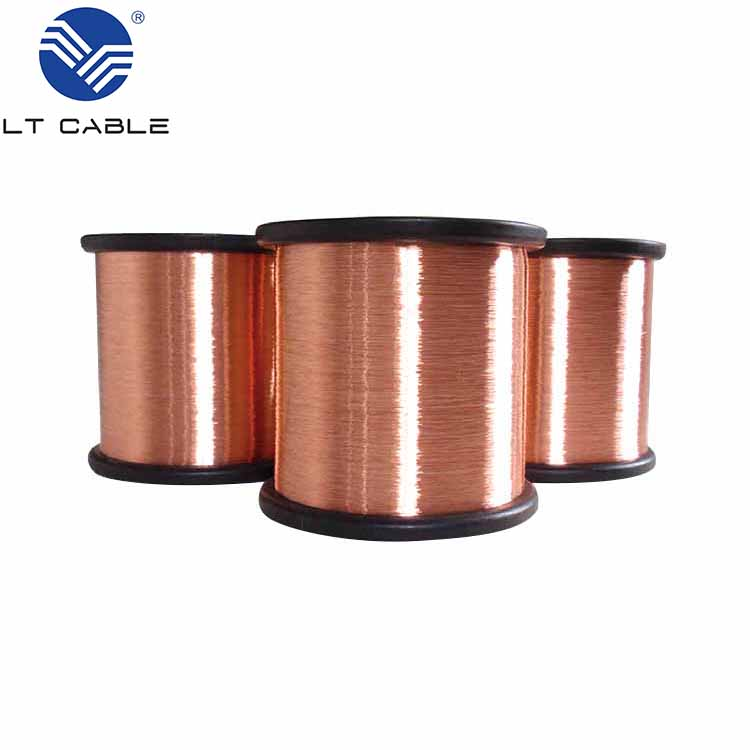
Why CCS Wire Outperforms CCA Wire in Grounding Applications
Conductivity-corrosion balance: How CCS delivers superior long-term performance vs. CCA wire
Selecting a conductor for grounding systems demands more than just initial conductivity—it requires balancing electrical performance with decades of mechanical and electrochemical integrity. Copper-Clad Steel (CCS) wire achieves this balance far more effectively than Copper-Clad Aluminum (CCA) wire.
CCA wire uses an aluminum core clad with copper, delivering only 55–60% of the conductivity of solid copper. While acceptable for lightweight signal applications, its higher resistivity poses real risks in fault-current scenarios: increased heat generation and voltage drop compromise safety and system reliability in critical grounding paths. Worse, aluminum’s inherent brittleness makes it prone to bending fatigue during installation or ground movement—leading to premature strand failure. Even more critically, when the thin copper cladding is scratched or compromised, the resulting galvanic couple between copper and aluminum accelerates internal corrosion. This localized decay rapidly reduces cross-sectional area and can cause complete conductor failure well before the end of its intended service life.
In contrast, CCS wire features a high-strength steel core metallurgically bonded to a thick copper cladding. The steel core provides 2–3× the break-load strength of solid copper, ensuring mechanical resilience during installation—even in rocky or compacted soils. From a corrosion standpoint, steel and copper form a more stable galvanic pair than aluminum and copper, and the substantial copper cladding acts as a durable barrier. Even in aggressive environments where the outer layer eventually degrades, the robust steel core preserves structural continuity and grounding functionality. This dual advantage—mechanical durability plus predictable, slow corrosion—makes CCS uniquely suited to meet the 30+ year service life expected in utility, industrial, and commercial grounding systems.
IEEE Std 80-2019 validation: CCS corrosion resistance in high-chloride and acidic soils
The performance of CCS in aggressive underground environments is not anecdotal—it is codified in IEEE Std 80-2019, the industry’s definitive standard for substation grounding design. This standard explicitly acknowledges CCS as a reliable grounding material due to its predictable, long-term corrosion behavior across diverse soil chemistries. Unlike bimetallic conductors where minor cladding damage triggers rapid galvanic decay, CCS benefits from a reversed electrochemical dynamic: in many soil conditions, the steel core acts protectively—slowing copper layer loss rather than accelerating it.
Field experience confirms this: thickly clad CCS conductors maintain low-resistance earth connections for decades in high-chloride coastal zones and acidic soils that would severely degrade galvanized steel rods—or completely compromise CCA wire. As a result, leading engineering guides and manufacturers specializing in bimetallic grounding solutions permit direct-burial use of CCS across a broad pH range and varying levels of soil aggressivity, supporting safe, maintenance-free earthing over the full design life.
Key CCS Wire Specifications for Reliable Earthing Systems
IEC 62561-2 compliance: Minimum 25 mm² cross-section, ≥370 MPa tensile strength, and adhesion requirements
IEC 62561-2 establishes rigorous performance benchmarks for earthing conductors—and CCS wire meets all three critical criteria where CCA fails. First, the standard mandates a minimum cross-section of 25 mm² to ensure adequate current-carrying capacity and mechanical robustness under installation stress and long-term soil loading. Second, it requires a tensile strength of at least 370 MPa—a threshold easily satisfied by CCS’s steel core, even in hard-pan or high-compaction soils. Third, cladding adhesion must be metallurgically sound: the copper layer must remain bonded through bending, thermal cycling, and corrosive exposure. Independent testing per IEC 62561-2 annexes verifies that quality-manufactured CCS achieves peel strengths exceeding 10 N/mm²—comparable to solid copper. This tripartite compliance ensures CCS performs reliably across its full 30-year design life.
Galvanic compatibility with common ground rods: CCS vs. copper-bonded, galvanized, and stainless steel
Grounding system longevity depends heavily on galvanic compatibility between conductor and electrode. CCS wire’s copper cladding aligns closely with copper-bonded steel rods, minimizing electrochemical risk. With other rod types, careful interface design is required:
| Ground rod material | Electrochemical potential vs. CCS wire | Galvanic corrosion risk | Recommended connection strategy |
|---|---|---|---|
| Copper-bonded steel | Nearly identical potential (≈0.0 V) | Negligible | Direct exothermic weld or clamp |
| Galvanized steel (zinc) | CCS is cathodic to zinc (≈0.3 V) | Moderate – zinc may corrode preferentially | Use stainless steel intermediate or isolation kit |
| Stainless steel (304/316) | Slight cathode-to-anode difference (≈0.1 V) | Low, but possible in acidic soils | Direct connection acceptable; avoid dissimilar metal in salty environments |
For copper-bonded rods—the most widely used grounding electrode—CCS is the natural pairing, enabling seamless, low-risk connections. When used with galvanized rods, the zinc coating sacrifices itself to protect the CCS wire, potentially shortening rod life; dielectric isolation or stainless transition pieces mitigate this. Stainless rods present minimal risk, but in highly conductive soils (30 Ω·m), localized corrosion can occur—exothermic welding with copper-based filler eliminates the galvanic interface entirely.
Soil-Driven Selection Criteria for CCS Grounding Wire
Soil resistivity thresholds (≥30 Ω·m) where CCS replaces bare copper for cost-performance optimization
Soil resistivity governs grounding system design—and above ~30 Ω·m, the surrounding earth—not the conductor—becomes the dominant factor limiting current dissipation. As IEEE Std 80-2013 explains, the marginal conductivity advantage of pure copper (2–5%) becomes functionally irrelevant in these conditions. EPRI field data (2021) confirms that CCS and bare copper conductors of identical diameter yield ground resistances within 1 Ω even at 50 Ω·m—validating CCS as a technically equivalent, economically superior alternative. At 40–60% lower cost per linear foot, CCS delivers significant material savings without sacrificing performance.
Unlike CCA wire—which suffers rapid galvanic attack in moist, high-resistivity backfills—CCS maintains mechanical compliance with IEC 62561-2 while eliminating the need for costly all-copper installations. This soil-driven selection rule prevents over-specification: engineers confidently specify CCS where resistivity exceeds 30 Ω·m, optimizing total installed cost without compromising safety, longevity, or code compliance.
Proper Connection Methods to Ensure CCS Wire Integrity at Ground Rod Interfaces
Exothermic welding best practices for CCS: Achieving metallurgical bond integrity per UL 467
Exothermic welding remains the gold standard for permanent, low-impedance connections between CCS wire and ground rods—provided it’s executed to UL 467 (Standard for Grounding and Bonding Equipment) requirements. Success hinges on surface preparation: both wire and rod surfaces must be clean, dry, and free of oxidation, grease, or corrosion.
Use a graphite mold and weld cartridge precisely matched to the CCS wire’s diameter and copper-cladding thickness. Crucially, CCS’s steel core withstands the exothermic reaction’s extreme temperatures—unlike CCA, whose aluminum core can melt or deform, undermining joint integrity. After ignition, allow molten copper alloy to fully flow into the cavity and cool undisturbed. Post-weld inspection should confirm full fusion, absence of voids or cracks, and a measured joint resistance below 5 milliohms. This process yields a corrosion-resistant, molecularly bonded connection that retains full mechanical strength and electrical continuity—meeting UL 467’s performance and safety expectations for critical grounding infrastructure.
Frequently Asked Questions
Why is CCS wire better than CCA wire for grounding applications?
CCS wire has a stronger steel core, higher conductivity, and superior corrosion resistance compared to CCA wire. Unlike CCA, which suffers galvanic decay and bending fatigue, CCS wire maintains long-term mechanical and electrochemical integrity.
Can CCS wire be used in high-chloride and acidic soils?
Yes, CCS wire is recognized as a reliable grounding material in aggressive underground environments, including high-chloride and acidic soils, as per IEEE Std 80-2019.
What is the recommended method to connect CCS wire to ground rods?
Exothermic welding is the best practice for connecting CCS wire to ground rods. It creates a durable, low-impedance joint that meets UL 467 standards.
How does CCS wire comply with IEC 62561-2 standards?
CCS wire meets the minimum cross-section, tensile strength, and cladding adhesion criteria outlined in IEC 62561-2, ensuring reliable long-term performance.
When should CCS wire replace bare copper in grounding systems?
CCS wire is recommended in soils with resistivity greater than 30 Ω·m, as it offers equivalent performance to bare copper while being more cost-effective.
Table of Contents
- Why CCS Wire Outperforms CCA Wire in Grounding Applications
- Key CCS Wire Specifications for Reliable Earthing Systems
- Soil-Driven Selection Criteria for CCS Grounding Wire
- Proper Connection Methods to Ensure CCS Wire Integrity at Ground Rod Interfaces
-
Frequently Asked Questions
- Why is CCS wire better than CCA wire for grounding applications?
- Can CCS wire be used in high-chloride and acidic soils?
- What is the recommended method to connect CCS wire to ground rods?
- How does CCS wire comply with IEC 62561-2 standards?
- When should CCS wire replace bare copper in grounding systems?


