 EN
EN

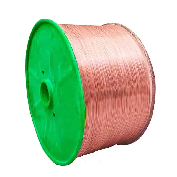
Why Tin Coating Thickness Matters for TCCA Wire Performance
Tin coating thickness directly dictates the reliability and lifespan of TCCA wire in demanding applications. A coating below 0.5 µm fails to provide adequate barrier protection, leaving the copper core vulnerable to oxidation and corrosion—especially in high-humidity or saline environments—accelerating contact resistance rise and premature failure. Conversely, a layer exceeding 3.0 µm promotes brittle intermetallic compound (IMC) growth at the copper–tin interface during thermal cycling or soldering, compromising mechanical integrity. Thickness also governs solderability: an optimal layer ensures rapid, uniform wetting and strong joint formation, while insufficient coverage causes poor wetting and weak connections. For TCCA wire used in industrial, marine, or automotive electrical systems, maintaining the precise 0.5–3.0 µm range is critical to balancing long-term corrosion resistance, consistent electrical performance, and robust solder joints—without introducing brittleness. Rigorous thickness control is therefore not a quality option but a fundamental performance requirement.
Industry Standards and Acceptable Tin Thickness Ranges for TCCA Wire
Tin coating thickness governs the performance and reliability of TCCA (tin-coated copper-clad aluminum) wire. Adherence to established industry standards ensures consistent electrical and mechanical properties across applications. This section outlines key specifications and the practical implications of the acceptable thickness window.
ASTM B799-18 and IPC-4552A Requirements for TCCA Wire Tin Plating
Two principal standards define test methods and acceptance criteria for tin coatings on wire. ASTM B799-18 specifies the procedure for determining coating thickness using microscopic examination of cross sections—a direct, traceable measurement requiring the coating to be continuous and free of cracks or pores that expose the underlying aluminum or copper cladding. For TCCA wire, the standard mandates reporting the minimum thickness observed around the circumference—not an average—to reflect worst-case coverage.
IPC-4552A, though written for immersion tin on printed circuit boards, provides widely adopted principles for tin plating continuity and uniformity. Its minimum thickness guidance—0.8 µm—is commonly applied to TCCA wire to ensure sufficient coverage over the copper-clad aluminum core and reliable solderability under real-world conditions. Compliance with both standards verifies that the tin layer will withstand oxidation, maintain low contact resistance, and form durable solder joints in harsh service environments.
Optimal Thickness Range (0.5–3.0 µm) and Its Impact on Solderability, Corrosion Resistance, and Intermetallic Formation
The ideal tin thickness on TCCA wire falls between 0.5 µm and 3.0 µm. Below 0.5 µm, incomplete coverage risks exposing base metal to oxidation and reduces solderability; above 3.0 µm, excessive IMC growth during soldering may embrittle the interface. The table below summarizes the effect of thickness on critical performance attributes.
| Tin Thickness (µm) | Solderability | Corrosion Resistance | Intermetallic Formation |
|---|---|---|---|
| < 0.5 | Poor | Low | Minimal, but base metal oxidation risk |
| 0.5–1.5 | Excellent | Excellent | Thin, beneficial IMC layer |
| 1.5–3.0 | Good | Very good | Moderate, acceptable for most applications |
| 3.0 | Variable | Good | Thick IMC layer may cause embrittlement |
A 2022 study by a leading wire manufacturer found that TCCA wire with 1.0 µm tin maintained over 95% solder coverage after steam aging—demonstrating how this midpoint optimizes protection and joint strength. For indoor applications with minimal thermal stress, 0.5 µm may suffice; for automotive or marine use—where vibration, salt, and temperature swings are routine—1.5–2.5 µm is recommended. The goal is to avoid extremes: too little invites early failure; too much risks long-term embrittlement.
Lab-Based Testing Methods to Accurately Measure Tin Coating Thickness on TCCA Wire
Cross-Sectional Metallography + SEM-EDS: Definitive Material and Thickness Verification
Cross-sectional metallography paired with Scanning Electron Microscopy and Energy Dispersive X-ray Spectroscopy (SEM-EDS) provides the most authoritative measurement of tin coating thickness on TCCA wire. The process involves precisely cutting a wire cross-section, mounting it in epoxy, and polishing to a mirror finish. SEM imaging reveals the distinct tin layer, while EDS confirms its elemental composition. As a destructive reference method, it delivers calibrated accuracy: per ASTM B748-20, this technique resolves individual layer thicknesses to within ±0.1 µm—essential for verifying compliance with the tight 0.5–3.0 µm tolerance band required for reliable solderability and corrosion protection. Industry labs routinely use this method as the “gold standard” to calibrate faster, non-destructive instruments.
XRF Analysis: Non-Destructive, Quantitative Tin Thickness and Surface Composition Assessment
X-ray Fluorescence (XRF) analysis offers a rapid, non-destructive alternative for measuring tin thickness on TCCA wire, making it ideal for production-line quality control. The technique bombards the wire surface with high-energy X-rays, causing tin atoms to emit characteristic fluorescent signals whose intensity correlates directly with coating thickness. XRF can simultaneously quantify tin thickness and detect unintended intermetallic phases or alloy variations. Per ISO 3497:2018, modern handheld XRF units achieve a relative precision of ±2% for tin layers thicker than 0.5 µm on copper substrates. Because TCCA wire features a copper cladding beneath the tin, XRF readings remain largely unaffected by the aluminum core—delivering accurate, repeatable results without sample preparation. This method is widely adopted for routine inspections and real-time process control.
Practical Field Assessment Techniques for TCCA Wire Tin Coating Integrity
Visual Inspection, Microscopic Evaluation, and Bend Testing as Correlative Indicators of Adequate Tin Coverage
Field-based checks do not measure exact tin thickness but serve as quick, correlative gauges of plating integrity. Begin with a visual survey under bright light: a uniform, matte-silver surface—free of discoloration, exposed copper, or blistering—suggests continuous coverage. A portable digital microscope (≥50×) then reveals surface texture; a smooth, fine-grained appearance indicates sound plating, while rough, pitted, or flaking zones signal inadequate adhesion or early corrosion. A simple bend test around a mandrel eight to ten times the wire diameter further exposes weak tin-to-substrate bonds. Cracking or peeling at the bend radius confirms poor coating adherence; clean, ductile deformation without flaking supports acceptable coverage. Together, these three methods—visual, microscopic, and mechanical—provide a practical, immediate assessment of tin coating health on TCCA wire in the field.
FAQs
What is the optimal tin coating thickness for TCCA wire?
The optimal tin coating thickness for TCCA wire is between 0.5 µm and 3.0 µm. This range balances corrosion resistance, solderability, and mechanical integrity.
Why is tin coating thickness below 0.5 µm problematic?
Thickness below 0.5 µm fails to provide sufficient protection, leaving the copper core vulnerable to oxidation and resulting in reduced solderability and increased risk of corrosion.
What are the consequences of exceeding 3.0 µm in tin coating thickness?
Exceeding 3.0 µm can lead to excessive growth of brittle intermetallic compounds, which compromise mechanical integrity and can result in long-term embrittlement.
How can tin coating thickness be accurately measured?
Accurate measurement can be done through cross-sectional metallography paired with SEM-EDS or non-destructive XRF analysis.
Are there field methods for assessing tin coating quality?
Yes, visual inspection, microscopic evaluation, and bend testing are practical methods to assess tin coating quality in the field.


