Copper Coated Aluminum Wire: Lightweight & High-Conductivity CCA Wire

Get a Free Quote

Our representative will contact you soon.
Name
Email
Mobile
Country/Region
Choose the product you want
Message
0/1000
Unmatched Performance of Copper Coated Aluminum Wire

Unmatched Performance of Copper Coated Aluminum Wire

Copper coated aluminum wire combines the lightweight properties of aluminum with the excellent conductivity of copper. This unique combination results in a wire that is not only lighter than pure copper but also offers superior electrical performance. Our copper coated aluminum wire is corrosion-resistant, making it ideal for various applications in harsh environments. With our fully automated production lines, we ensure consistent quality and precision in every strand. This wire is perfect for industries that require high efficiency and durability, such as telecommunications, automotive, and renewable energy sectors.
Get A Quote

Case Studies

Transforming Telecommunications with Copper Coated Aluminum Wire

In a recent project with a leading telecommunications company, our copper coated aluminum wire was selected for its superior conductivity and lightweight properties. The client faced challenges with traditional copper wires that were too heavy and costly. By switching to our copper coated aluminum wire, they reduced installation costs by 30% and improved signal quality significantly. The wire's resistance to corrosion ensured longevity in outdoor applications, leading to a 25% reduction in maintenance costs over five years. This case highlights how our product can solve critical issues in telecommunications infrastructure.

Enhancing Automotive Efficiency

A renowned automotive manufacturer approached us to improve their vehicle wiring systems. They required a solution that minimized weight while maximizing electrical performance. Our copper coated aluminum wire was the ideal choice, enabling them to reduce the overall weight of their vehicles by 15%. This not only enhanced fuel efficiency but also contributed to lower emissions. The wire's durability and resistance to environmental factors ensured that their vehicles met stringent industry standards. This project demonstrates the effectiveness of our product in the automotive sector.

Revolutionizing Renewable Energy Solutions

In collaboration with a leading renewable energy firm, our copper coated aluminum wire was utilized in solar panel installations. The lightweight nature of the wire allowed for easier handling and installation, significantly reducing labor costs. Additionally, the enhanced conductivity ensured maximum energy transfer from solar panels to inverters, optimizing overall system performance. The client reported a 20% increase in energy efficiency compared to previous installations using traditional wiring. This case illustrates the adaptability of our wire in renewable energy applications.

Related products

Copper coated aluminum wire provides the best lightweight properties of aluminum and the best conductivity of copper. Litong Cable has fully automated production lines that manufacture wire to the highest standards and consistent quality. From the selection of the raw materials to the final inspection of the product, every step in the production of our wires is carefully monitored. The wires are coated in copper which increases conductivity and protects aluminum from corrosion. This makes our wires ideal for many different environments. Different industries have different needs and we provide customized solutions to meet those needs. Quality and customer satisfaction motivates us to keep expanding and improving our product lines.

Frequently Asked Questions about Copper Coated Aluminum Wire

What are the main benefits of using copper coated aluminum wire?

Copper coated aluminum wire offers enhanced conductivity, reduced weight, and excellent corrosion resistance, making it ideal for various applications.
The copper coating significantly improves the electrical conductivity of aluminum wire, allowing for efficient power transmission while maintaining a lightweight profile.

Related article

CCA Wire Manufacturing Process: Cladding vs Plating

15

Jan

CCA Wire Manufacturing Process: Cladding vs Plating

Core Metallurgical Differences Between Cladding and Plating for CCA Wire

Bond Formation: Solid-State Diffusion (Cladding) vs Electrochemical Deposition (Plating)

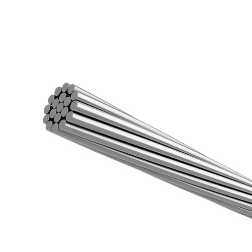
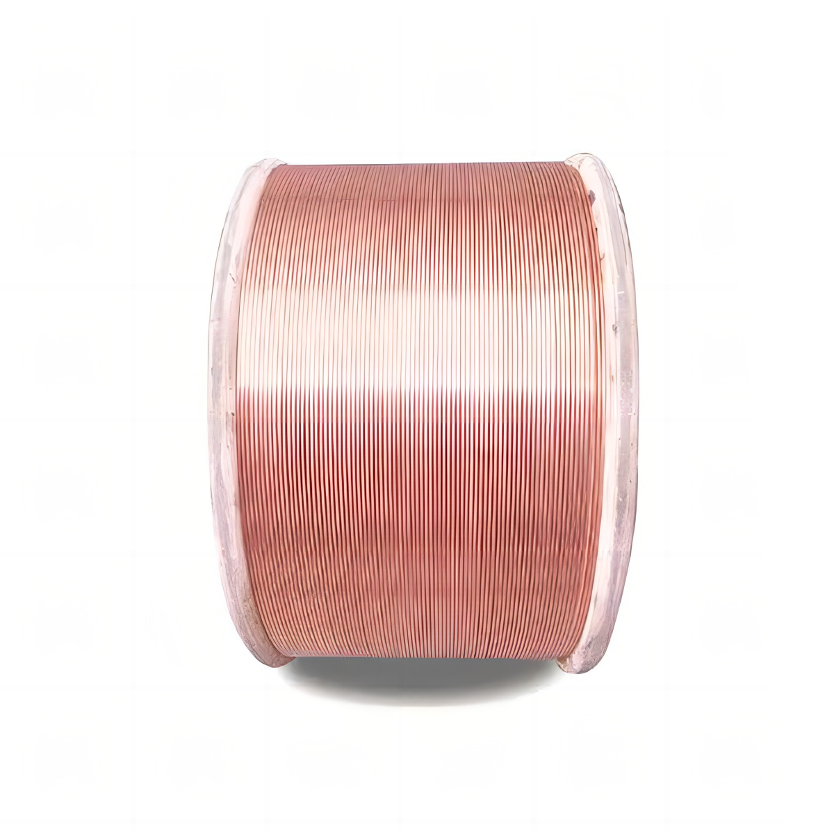
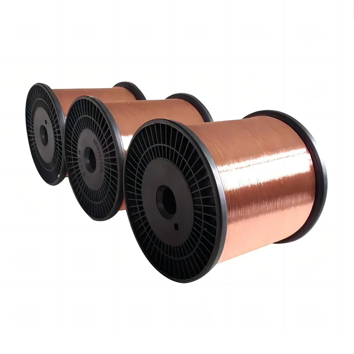
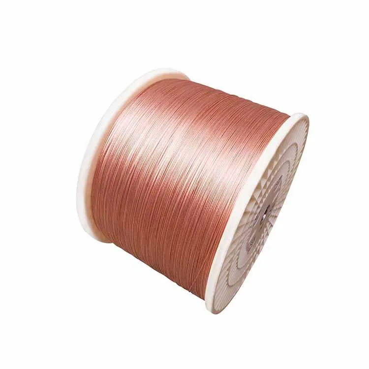
The production of Copper-Clad Aluminum (CCA) wire involves two completely different approaches when it comes to combining metals. The first method is called cladding, which works through what’s known as solid state diffusion. Basically, manufacturers apply intense heat and pressure so that copper and aluminum atoms actually start mixing at the atomic level. What happens then is pretty remarkable - these materials form a strong, lasting bond where they become one at the microscopic level. There's literally no clear boundary between the copper and aluminum layers anymore. On the other side of things we have electroplating. This technique works differently because instead of mixing atoms together, it simply deposits copper ions onto aluminum surfaces using chemical reactions in water baths. The connection here isn't as deep or integrated though. It's more like sticking things together with glue rather than fusing them at the molecular level. Because of this difference in bonding, wires made through electroplating tend to separate more easily when subjected to physical stress or temperature changes over time. Manufacturers need to be aware of these differences when choosing their production methods for specific applications.

Interface Quality: Shear Strength, Continuity, and Cross-Sectional Homogeneity

Interfacial integrity directly governs CCA wire’s long-term reliability. Cladding yields shear strengths exceeding 70 MPa due to continuous metallurgical fusion—validated by standardized peel tests—and cross-sectional analysis shows homogeneous blending without voids or weak boundaries. Plated CCA, however, faces three persistent challenges:

  • Discontinuity risks, including dendritic growth and interfacial voids from non-uniform deposition;
  • Reduced adhesion, with industry studies reporting 15–22% lower shear strength than clad equivalents;
  • Delamination susceptibility, especially during bending or drawing, where poor copper penetration exposes the aluminum core.

Because plating lacks atomic diffusion, the interface becomes a preferential site for corrosion initiation—particularly in humid or saline environments—accelerating degradation where the copper layer is compromised.

Cladding Methods for CCA Wire: Process Control and Industrial Scalability

Hot Dip and Extrusion Cladding: Aluminum Substrate Preparation and Oxide Disruption

Getting good results from cladding starts with proper prep work on aluminum surfaces. Most shops use either grit blasting techniques or chemical etching processes to strip away that natural oxide layer and create just the right amount of surface roughness around 3.2 micrometers or less. This helps the materials bond better together over time. When we talk about hot dip cladding specifically, what happens is pretty straightforward but requires careful control. The aluminum parts get dipped into molten copper heated between roughly 1080 to 1100 degrees Celsius. At those temperatures, the copper actually starts working its way through any remaining oxide layers and begins diffusing into the base material. Another approach called extrusion cladding works differently by applying massive amounts of pressure somewhere between 700 and 900 megapascals. This forces the copper into those clean areas where there were no oxides left behind through what's known as shear deformation. Both these methods are great for mass production needs too. Continuous extrusion systems can run at speeds approaching 20 meters per minute, and quality checks using ultrasonic testing typically show interface continuity rates above 98% when running full scale commercial operations.

Sub-Arc Welding Cladding: Real-Time Monitoring for Porosity and Interfacial Delamination

In submerged arc welding (SAW) cladding processes, copper gets deposited beneath a protective layer of granular flux. This setup really cuts down on oxidation problems while giving much better control over the heat during the process. When it comes to quality checks, high speed X ray imaging at around 100 frames per second can spot those tiny pores smaller than 50 microns as they form. The system then automatically tweaks things like voltage settings, how fast the weld moves along, or even adjusts the flux feeding rate accordingly. Keeping track of temperature is also super important. The heat affected zones need to stay below about 200 degrees Celsius to stop aluminum from getting all messed up with unwanted recrystallization and grain growth that weakens the base material. After everything's done, peel tests regularly show adhesion strengths above 15 Newtons per millimeter, which meets or beats the standards set by MIL DTL 915. Modern integrated systems can handle between eight to twelve wire strands at once, and this has actually cut down on delamination issues by roughly 82% across various manufacturing facilities.

Electroplating Process for CCA Wire: Adhesion Reliability and Surface Sensitivity

Pre-Treatment Criticality: Zincate Immersion, Acid Activation, and Etch Uniformity on Aluminum

When it comes to getting good adhesion on electroplated CCA wires, surface prep matters more than almost anything else. Aluminum naturally forms this tough oxide layer that gets in the way of copper sticking properly. Most untreated surfaces just don't pass adhesion tests, with research from last year showing failure rates around 90%. The zincate immersion method works well because it lays down a thin, even layer of zinc that acts as a kind of bridge for copper to deposit onto. With standard materials like AA1100 alloy, using acid solutions with sulfuric and hydrofluoric acids creates those tiny pits across the surface. This raises surface energy somewhere between 40% to maybe 60%, which helps ensure the plating spreads out evenly instead of clumping together. When etching isn't done right, certain spots become weak points where the coating might come off after repeated heating cycles or when bent during manufacturing. Getting the timing right makes all the difference. About 60 seconds at room temperature with a pH level around 12.2 gives us zinc layers thinner than half a micrometer. If these conditions aren't met exactly, the bond strength drops dramatically, sometimes by as much as three quarters.

Copper Plating Optimization: Current Density, Bath Stability, and Adhesion Validation (Tape/Bend Tests)

The quality of copper deposits really hinges on keeping those electrochemical parameters under tight control. When it comes to current density, most shops aim for between 1 and 3 amps per square decimeter. This range gives a good balance between how fast the copper builds up and the resulting crystal structure. Go over 3 A/dm² though, and things get problematic fast. The copper grows too quickly in dendritic patterns that will crack right up when we start pulling wires later on. Maintaining bath stability means watching copper sulfate levels closely, typically keeping them somewhere between 180 and 220 grams per liter. Don't forget about those brightener additives either. If they run low, the risk of hydrogen embrittlement jumps by around 70%, which nobody wants to deal with. For adhesion testing, most facilities follow ASTM B571 standards, wrapping samples 180 degrees around a mandrel. They also do tape tests according to IPC-4101 specifications using about 15 newtons per centimeter pressure. The goal is no flaking after 20 tape pulls straight through. If something fails these tests, it's usually pointing to problems with bath contamination or poor pre-treatment processes rather than any fundamental issues with the materials themselves.

Performance Comparison of CCA Wire: Conductivity, Corrosion Resistance, and Drawability

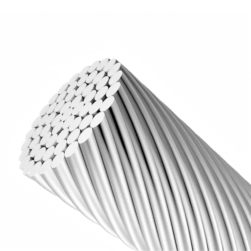
Copper Clad Aluminum (CCA) wire comes with certain performance limitations when looking at three key factors. The conductivity typically sits between 60% to 85% of what pure copper offers according to IACS standards. This works okay for transmitting low power signals but falls short for high current applications where heat buildup becomes a real problem for both safety and efficiency. When it comes to resisting corrosion, the quality of the copper coating matters a lot. A solid, uninterrupted copper layer protects the aluminum underneath pretty well. But if there's any kind of damage to this layer - maybe from physical impacts, tiny pores in the material, or layers coming apart at the boundary - then the aluminum gets exposed and starts corroding much faster through chemical reactions. For outdoor installations, extra protective coatings made of polymers are almost always necessary, particularly in areas with regular moisture. Another important consideration is how easy the material can be shaped or drawn without breaking. Hot extrusion processes work better here since they maintain the bond between materials even after multiple shaping steps. Electroplated versions tend to have problems though because their connection isn't as strong, leading to separation issues during manufacturing. All told, CCA makes sense as a lighter weight, cheaper option compared to pure copper in situations where electrical requirements aren't too demanding. Still, it definitely has its limits and shouldn't be considered a one-size-fits-all replacement.

View More
CCA Wire for Automotive Harness: Pros, Cons, and Standards

22

Jan

CCA Wire for Automotive Harness: Pros, Cons, and Standards

Why Automotive OEMs Are Adopting CCA Wire: Weight, Cost, and EV-Driven Demand

EV Architecture Pressures: How Lightweighting and System Cost Targets Accelerate CCA Wire Adoption

The electric vehicle industry has two big challenges on its plate right now - making cars lighter to boost battery range while keeping component costs down. Copper clad aluminum (CCA) wire helps tackle both issues at once. It cuts weight by around 40% compared to regular copper wire, yet still manages about 70% of copper's conductivity according to research from Canada's National Research Council last year. Why does this matter? Because EVs need roughly 1.5 to 2 times more wiring than traditional gasoline powered vehicles, particularly when it comes to those high voltage battery packs and fast charging infrastructure. The good news is aluminum costs less upfront, which means manufacturers can save money overall. These savings aren't just pocket change either; they free up resources for developing better battery chemistries and integrating advanced driver assistance systems. There's one catch though: thermal expansion properties differ between materials. Engineers have to pay close attention to how CCA behaves under heat changes, which is why proper termination techniques following SAE J1654 standards are so important in production environments.

Real-World Deployment Trends: Tier-1 Supplier Integration in High-Voltage Battery Harnesses (2022–2024)

More Tier 1 suppliers are turning to CCA wire for their high voltage battery harnesses on those 400V plus platforms. The reason? Localized weight reductions really boost pack level efficiency. Looking at validation data from about nine major electric vehicle platforms across North America and Europe between 2022 and 2024, we see most of the action happening in three main spots. First there's those inter cell busbar connections which account for roughly 58% of what's going on. Then comes the BMS sensor arrays and finally the DC/DC converter trunk cabling. All these setups meet ISO 6722-2 and LV 214 standards too, including those tough accelerated aging tests that prove they can last around 15 years. Sure, the crimp tools need some adjustments because of how CCA expands when heated, but manufacturers still find themselves saving approximately 18% per harness unit when switching from pure copper options.

Engineering Trade-offs of CCA Wire: Conductivity, Durability, and Termination Reliability

Electrical and Mechanical Performance vs. Pure Copper: Data on DC Resistance, Flex Life, and Thermal Cycling Stability

CCA conductors have about 55 to 60 percent more DC resistance compared to copper wires of the same gauge size. This makes them more prone to voltage drops in circuits carrying large currents such as those found in battery main feeds or BMS power rails. When it comes to mechanical properties, aluminum just isn't as flexible as copper. Standardized bend tests reveal that CCA wiring usually breaks down after around 500 flex cycles maximum, whereas copper can handle over 1,000 cycles before failing under similar conditions. Temperature fluctuations pose another problem too. The repeated heating and cooling experienced in automotive environments ranging from minus 40 degrees Celsius up to 125 degrees creates stress at the interface between copper and aluminum layers. According to testing standards like SAE USCAR-21, this kind of thermal cycling can boost electrical resistance by roughly 15 to 20 percent after just 200 cycles, which significantly impacts signal quality especially in areas subject to constant vibration.

Crimp and Solder Interface Challenges: Insights from SAE USCAR-21 and ISO/IEC 60352-2 Validation Testing

Getting termination integrity right remains a major challenge in CCA manufacturing. Tests according to SAE USCAR-21 standards have shown that aluminum tends to experience cold flow issues when subjected to crimp pressure. This problem leads to around 40% more pull-out failures if the compression force or die geometry isn't just right. The solder connections also struggle with oxidation at where copper meets aluminum. Looking at ISO/IEC 60352-2 humidity tests, we see mechanical strength drops by as much as 30% compared to regular copper solder joints. Top automotive manufacturers try to get around these problems by using nickel plated terminals and special inert gas soldering techniques. Still, nothing beats copper when it comes to lasting performance over time. Because of this, detailed micro section analysis and rigorous thermal shock testing are absolute musts for any component going into high vibration environments.

Standards Landscape for CCA Wire in Automotive Harnesses: Compliance, Gaps, and OEM Policies

Key Standards Alignment: UL 1072, ISO 6722-2, and VW 80300 Requirements for CCA Wire Qualification

For automotive grade CCA wire, meeting all sorts of overlapping standards is pretty much essential if we want safe, durable wiring that actually works properly. Take UL 1072 for instance. This one deals specifically with how well medium voltage cables resist fires. The test here requires CCA conductors to survive flame propagation tests at around 1500 volts. Then there's ISO 6722-2 which focuses on mechanical performance. We're talking about at least 5000 flex cycles before failure plus good abrasion resistance even when exposed to under hood temperatures reaching 150 degrees Celsius. Volkswagen throws another curveball with their VW 80300 standard. They demand exceptional corrosion resistance from high voltage battery harnesses, requiring them to withstand salt spray exposure for over 720 hours straight. All told, these various standards help confirm whether CCA can really work in electric vehicles where every gram counts. But manufacturers need to keep an eye on conductivity losses too. After all, most applications still require performance within 15% of what pure copper delivers as a baseline.

The OEM Divide: Why Some Automakers Restrict CCA Wire Despite IEC 60228 Class 5 Acceptance

While the IEC 60228 Class 5 standard does allow for conductors with higher resistance such as CCA, most original equipment manufacturers have drawn clear lines about where these materials can be used. Typically, they limit CCA to circuits that draw less than 20 amps and completely ban it from any system where safety is a concern. The reason behind this restriction? There are still reliability issues. Testing shows that aluminum connections tend to develop about 30 percent more contact resistance over time when subjected to temperature changes. And when it comes to vibrations, CCA crimp connections break down almost three times quicker than copper ones according to SAE USCAR-21 standards in those vehicle harnesses mounted on suspensions. These test results highlight some serious holes in current standards, especially regarding how these materials hold up against corrosion over years of service and under heavy loads. As a result, car makers base their decisions more on what actually happens in real world conditions rather than just ticking boxes on compliance paperwork.

View More
Maximizing Solar Energy Output with Proper Photovoltaic Wiring

22

Mar

Maximizing Solar Energy Output with Proper Photovoltaic Wiring

## Photovoltaic Wiring Fundamentals for Solar Power Efficiency

Key Electrical Terms: Voltage, Current, and Power

Getting a handle on basic electrical terms like voltage (V), current (I), and power (P) makes all the difference when trying to get the most out of solar panels. Power basically comes from multiplying voltage, which acts like electrical pressure, with current, the flow rate of electricity, so P equals V times I. These three factors really affect how well a solar system turns sunlight into electricity we can actually use. Take shading problems for example. When parts of the panel get shaded or temperatures swing too much, voltage drops below what's needed, and suddenly the inverter isn't working right anymore. That means less electricity coming out at the end of the day. Research from NREL shows just how big of a hit systems take when voltage and current aren't properly managed. So knowing these fundamentals isn't just theory stuff it directly impacts whether homeowners and businesses actually benefit from their solar investments.

Stranded Wire vs. Solid Wire: Performance Considerations

Choosing between stranded and solid wire matters a lot when setting up photovoltaic systems. Stranded wire consists of many small strands twisted together, giving it much better flexibility than solid wire made from one continuous conductor. This makes all the difference during installation, especially in places where wires get shaken around or moved frequently. Solar installers tend to go for stranded wire outdoors since it handles the rough treatment of weather changes and physical stress much better. One major solar company actually reported seeing far fewer problems with connections on their systems using stranded wire, even through harsh winter storms and summer heatwaves. For most PV setups, the combination of bendability and durability simply makes stranded wire the smarter option overall.

Copper vs. Copper-Clad Aluminum (CCA) Conductors

When it comes to photovoltaic systems, copper versus copper-clad aluminum (CCA) conductors bring different things to the table, mostly around how well they conduct electricity and what they cost. Copper is pretty much the gold standard when it comes to conductivity and lasts longer too, which means less current gets lost along the way and the whole system runs better overall. But let's face it, copper just costs more money compared to those CCA wires. Now CCA has its place too because it's cheaper, but there's a catch. These wires have higher resistance and tend to lose more voltage especially when running across long distances. For folks working within tight budgets or dealing with shorter wire runs, CCA might still work just fine. Some tests showed copper beats out CCA hands down when looking at energy savings and system longevity, even though it does come with a bigger price tag attached.

Optimizing Solar Panel Configurations

Series Wiring: Maximizing Voltage Output

When solar panels are wired in series, they get connected end to end in a straight line, which boosts the total voltage produced. This works because we connect the positive side of one panel to the negative side of the next one. The result? Higher voltage without changing the current level, so this arrangement makes sense when we need more voltage for good energy conversion. But there's a catch worth mentioning about shade problems in series setups. If even one panel gets shaded, the whole chain suffers performance loss. To combat this issue, installers often add bypass diodes that let electricity skip around shaded panels instead of getting blocked completely. Research indicates that series wiring does raise system voltage effectively, leading to improved results particularly in big installations where panels sit mostly out of shadows. For example, many commercial rooftops benefit from this configuration since their layout tends to avoid deep shading issues.

Parallel Wiring: Balancing Current and Shade Resilience

When setting up parallel wiring for solar panels, basically what happens is we connect all the positive ends together on one wire and all the negatives on another. This helps balance things out electrically and makes the whole system more resistant to problems caused by shade. Compared to series wiring where everything gets added together, parallel keeps the same voltage level but adds up the current instead. The big advantage comes when some panels get shaded while others don't. With parallel setup, those clean panels still work at full power without dragging down because of their shaded neighbors. Take urban installations for example, where trees or buildings cast shadows throughout the day. We've seen actual installations in city environments where switching to parallel wiring boosted energy production noticeably during these tricky shading periods. Makes sense why many installers prefer this approach in challenging locations.

Hybrid Series-Parallel Systems

When solar panels mix series and parallel wiring setups, they tend to perform better because they get the best parts from both methods. These hybrid arrangements actually boost voltage levels while keeping track of current flow, which means the system gathers energy more efficiently overall. They work really well in situations where the sun doesn't shine consistently across different areas or when panels need to be arranged in tricky shapes around buildings. The way these systems balance voltage and current helps them hit what we call the inverter's sweet spot for maximum power production all day long. Real world tests show these mixed systems can grab noticeably more electricity compared to standard setups, especially helpful for properties dealing with changing light conditions or shaded spots here and there. For property owners looking at their bottom line, this kind of setup often pays off faster since it makes better use of whatever sunlight is available.

Critical Factors in Photovoltaic System Efficiency

Temperature Effects on Wiring and Output

The way temperature affects wiring and how much electricity photovoltaic systems produce really matters when trying to get the most out of solar installations. When it gets hotter outside, those tiny solar cells actually work less efficiently because there's more resistance building up in the wires connecting everything together. So even if the sun is shining brightly, we might still see lower power production than expected. That's why many installers now look at materials that handle heat better, such as copper clad aluminum wire which conducts electricity well while staying cooler under stress. Research from Fraunhofer ISE shows something interesting too: every time the temperature goes above 25 degrees Celsius, solar panels lose about half a percent efficiency per degree. Keeping these panels at their ideal operating temperature isn't just good theory either it makes a real difference in what kind of returns people get from their investment in renewable energy.

UV-Resistant Insulation and Durability Standards

Insulation that resists UV damage is really important for keeping photovoltaic systems working well for longer. Without proper protection, wiring gets damaged by sunlight over time, which means the whole system starts to break down faster than it should. Most industry guidelines require materials to handle whatever Mother Nature throws at them outdoors, dealing with both hot days and cold nights plus constant sun exposure without falling apart. The folks at NREL did some tests on different materials and found that those resistant to UV actually last much longer than regular ones. Systems built with these better materials just keep performing consistently throughout their entire life cycle instead of dropping off suddenly after a few years.

Best Practices for Safe and Code-Compliant Installations

Following good practices when installing photovoltaic systems matters a lot for keeping things safe and getting maximum performance out of them. Proper grounding techniques, using the right kind of insulated wires, and sticking to NEC standards are all part of what makes installations work well over time. When done correctly, these steps help avoid dangerous situations and keep solar panels producing electricity efficiently for years instead of just months. Most professionals in the field will tell anyone who asks that skipping on code requirements often leads to problems down the road, including fire hazards and wasted energy production. Research from groups like SEIA backs this up, showing that solar installations which follow standard procedures tend to perform better and create fewer headaches for homeowners and businesses alike.

View More
Shielded Cables: The Backbone of Reliable Communications

22

Mar

Shielded Cables: The Backbone of Reliable Communications

Understanding Shielded Cables in Communication Networks

What Makes Shielded Cables Essential for Data Transmission?

Shielded cables are really important for keeping data safe during transmission since they block out external electromagnetic interference, or EMI as it's commonly called. We see this protection working well in places such as data centers and industrial areas where clear signals matter a lot. Take EMI for example it messes with signals and can cause problems like lost or corrupted data. Shielded cables help fix these issues by stopping those unwanted signals from getting through. Plus, these cables let data travel longer distances without losing strength, which makes them reliable across different situations. Industry studies show that switching from regular cables to shielded ones cuts down errors by around 80 percent, especially noticeable in spots with lots of EMI like manufacturing plants and hospitals.

Key Components: Enameled Wire and Conductive Materials

Enameled wire plays a big role in shielded cables because it offers excellent insulation and stands up well against corrosion issues. When installed properly, these wires help keep cables working reliably for years on end while shielding the inner conductors from outside damage and unwanted interference. Shielded cables often incorporate different metals too, with copper and aluminum being popular choices among manufacturers looking to boost conductivity and preserve signal integrity throughout their systems. Take copper for instance it has really high conductivity which means less resistance when transmitting signals, so data moves through the network much faster without losing strength along the way. Most professionals in the field will tell anyone who asks that using good quality materials during cable manufacturing isn't optional if companies want top notch performance out of their infrastructure since poor material selection directly affects how well those cables handle electromagnetic interference problems in real world conditions.

Stranded vs. Solid Wire in Cable Construction

When building cables, deciding between stranded and solid wire really comes down to what the job actually needs. Stranded wires bend better and hold up against wear and tear, so they work great when cables get moved around a lot or exposed to vibrations, think about car parts or factory equipment that moves constantly. Solid wire isn't as flexible but stands up to abuse much longer, which is why electricians usually go for this type when running power through walls or ceilings where things stay put. For sending signals through cables, stranded versions are harder to snap because they flex without breaking, though they do carry some extra resistance compared to their solid counterparts. Most people pick whichever fits their setup best, going with stranded if the cable will see action and sticking with solid for those permanent installations where stability matters most.

Electromagnetic Interference (EMI) and Signal Integrity

How EMI Disrupts Communication Network Performance

Electromagnetic interference, or EMI for short, really messes with how well communication networks work because it gets in the way of signals traveling through them. Most of the time this interference comes from other electrical devices sitting close by, and when it happens, important data either gets lost completely or becomes corrupted somehow. Take factories with lots of big machines running all day long, or places packed full of electronics - these spots tend to have constant problems with their signals getting disrupted, which makes everything run slower and less reliably. Looking at actual numbers shows something interesting too. Networks dealing with serious EMI issues lose way more data packets than they should, sometimes cutting down overall efficiency by around 30%. We've seen this happen in hospitals where doctors struggle to maintain reliable wireless connections because medical equipment creates so much EMI. That's why many tech professionals now recommend using shielded cables and other protective measures to keep networks functioning properly despite all the electromagnetic noise floating around.

The Role of Shielding in Preserving Signal Quality

Good shielding is essential for keeping signals clean since it blocks out unwanted electromagnetic interference. When cables get wrapped in conductive stuff like aluminum foil or copper braid, they create barriers against those pesky EM waves that mess with data transmission. Some studies indicate that certain methods work better than others. For instance, layering different materials together or mixing foil with braided shields tends to keep signal loss minimal even when dealing with those tricky high frequency transmissions. The field has seen some interesting developments lately too. Manufacturers are coming up with new conductive compounds and creative ways to build shields into cable structures. This progress should lead to stronger protection options down the road, especially important as our communication networks grow more complicated and operate under tougher conditions day after day.

Stranded Copper Wire Resistance Per Foot: Impact on EMI Protection

How much resistance there is in each foot of stranded copper wire really affects how well it blocks electromagnetic interference. Wires with lower resistance generally work better at stopping EMI, so picking the right gauge matters a lot. Take a look at what happens when we go down in wire gauge sizes. The resistance goes down too, which means better shielding against those pesky electromagnetic signals. According to some actual field tests from engineers working on this stuff daily, getting the wire size right for whatever environment it'll be used in makes all the difference for proper EMI protection. Anyone looking at installing wiring where strong EMI shielding is needed should definitely pay attention to these resistance numbers. Getting this part wrong could lead to problems later on with equipment malfunctioning or needing replacement sooner than expected.

Foil Shielding: Lightweight Protection for High-Frequency EMI

Foil shielding works really well at blocking out those pesky high frequency electromagnetic interferences (EMI) thanks to a thin metal layer wrapped around the cable. Usually made from copper or aluminum, this foil creates a complete barrier along the whole length of the cable. That's why we see it so much in areas plagued by high frequency signals. What sets foil apart from other shielding methods is how light it is. Installation becomes way simpler compared to bulkier options like braided shields. Sure, foil isn't as tough as some alternatives, but when weight matters most, like in tight spaces or long runs, it wins hands down. We find foil shielding all over the place actually. Data centers rely on it heavily because they can't afford signal disruptions. Same goes for telecom infrastructure where even small amounts of interference could cause major problems for communications networks.

Braided Shielding: Durability and Flexibility in Industrial Settings

Braided shielding consists of copper wires woven together into a mesh pattern, which gives it good strength while still being flexible enough for tough industrial conditions. Compared to foil shielding, this braided version covers around 70% to maybe even 95% of the surface area, though how well it works really depends on how tightly those wires are woven together. Industrial settings love this kind of shielding because it can take a beating without breaking down or losing function when subjected to harsh factory floor conditions. What makes braided shielding stand out is its flexibility factor too. Cables with this shielding can bend and move around all day long without affecting their performance. That's why we see so much of it in manufacturing plants where cables get moved around constantly and face plenty of mechanical stress over time.

Spiral Shielding Applications in Dynamic Communication Systems

Spiral shielding works really well in situations where cables get moved around a lot or bent frequently. The way the conductive material wraps around in spirals lets these cables stay flexible but still blocks out electromagnetic interference pretty effectively. That's why many engineers prefer them when dealing with equipment that moves constantly, think industrial robots or automated assembly lines for instance. Looking at recent developments, manufacturers keep finding ways to improve how these shields work better over time. With modern tech needing reliable connections even under tough conditions, we're seeing more companies switch to spiral shielding solutions across different sectors from manufacturing floors to medical devices.

Choosing the Right Shielded Cable for Communication Systems

Environmental Factors: EMI Sources and Cable Routing

Knowing where electromagnetic interference (EMI) comes from and how it travels matters a lot when picking out shielded cables for communication systems. Industrial equipment, old fashioned fluorescent lights, and nearby radio transmitters all create EMI that messes with signal quality. Getting the cable paths right helps reduce this problem. A good rule of thumb? Keep signal cables away from power lines and don't run them parallel. Also maintain some distance between sensitive signal lines and those pesky EMI sources. This becomes especially important in factories and plants where strong signals are needed. Real world experience tells us that cables kept at proper distances from EMI sources work better and maintain cleaner signals over time. Many engineers have seen this firsthand in their installations.

Balancing Conductivity and Flexibility: Bare Stranded Copper Wire Considerations

When selecting bare stranded copper wire, engineers need to weigh conductivity against flexibility based on what the job requires. The copper composition gives this type of wire outstanding electrical properties, which explains why it works so well in demanding applications like power transmission lines. But don't overlook the flexibility factor either. This characteristic makes installation easier in areas where components move around regularly, such as factory automation systems or vehicle wiring harnesses. Industry experience shows that stranded configurations retain their conductive qualities over longer runs while still bending around tight corners in cramped machinery compartments. Getting the mix right between these two attributes means better results down the road, whether the priority is maintaining signal strength through extended cable runs or accommodating frequent movements in mechanical assemblies.

Interpreting Stranded Wire Size Charts for Optimal Performance

Getting stranded wire size charts right makes all the difference when it comes to getting good cable performance. These charts basically tell us about wire sizes and how they impact things like impedance and what kind of electrical load they can handle. When picking the right size, we're looking at minimizing resistance along each foot of cable while keeping signals strong throughout the system. Otherwise, problems like cables getting too hot or losing signal strength become real headaches. A lot of folks miss important factors like temperature changes in the environment where the cables will be installed, or forget to check exactly what kind of load demands their particular setup has. Taking time to really understand these charts helps prevent those costly errors down the road, so communication systems run smoothly without unexpected issues popping up later on.

کردن: فهمیدن و استفاده از نمودارهای اندازه سیم فلزی برای عملکرد بهینه امری ضروری است که به کاهش مقاومت و بهبود انتقال سیگنال کمک می‌کند.

View More

Customer Experiences with Copper Coated Aluminum Wire

John Smith
Exceptional Performance for Telecommunications

Switching to Litong's copper coated aluminum wire has transformed our telecommunications projects. The weight reduction and improved conductivity have made a noticeable difference in our installations.

Sarah Johnson
Ideal for Automotive Applications

We have been using Litong's copper coated aluminum wire in our vehicles, and the results are impressive. The weight savings have contributed to better fuel efficiency and lower emissions, aligning with our sustainability goals.

Get a Free Quote

Our representative will contact you soon.
Email
Name
Company Name
Message
0/1000
Lightweight Yet Durable

Lightweight Yet Durable

Our copper coated aluminum wire is significantly lighter than traditional copper wire, making it easier to handle and install. This feature is particularly beneficial in applications where weight is a critical factor, such as in automotive and aerospace industries. The durability of the copper coating ensures that the wire can withstand harsh conditions without compromising performance, giving clients peace of mind in their investment.
Superior Conductivity

Superior Conductivity

The copper coating on our aluminum wire enhances its electrical conductivity, resulting in minimal energy loss during transmission. This property is crucial for industries that require efficient power transfer, such as renewable energy and telecommunications. By choosing our copper coated aluminum wire, clients can expect reduced energy costs and improved system performance, ultimately leading to greater operational efficiency.
  • Product Consultation & Selection

    Product Consultation & Selection

    Tailored advice, perfect fit solutions.

  • Production & Supply Chain

    Production & Supply Chain

    Efficient manufacturing, seamless supply.

  • Quality Assurance & Certification

    Quality Assurance & Certification

    Rigorous testing, global certifications.

  • Post-Sales Support & Tech Help

    Post-Sales Support & Tech Help

    Prompt assistance, ongoing support.

Get a Free Quote

Our representative will contact you soon.
Name
Email
Mobile
Country/Region
Title
Message
0/1000