Copper Plated Aluminum Wire: Lightweight, Conductive & Cost-Effective

Get a Free Quote

Our representative will contact you soon.
Name
Email
Mobile
Country/Region
Choose the product you want
Message
0/1000
Unmatched Benefits of Copper Plated Aluminum Wire

Unmatched Benefits of Copper Plated Aluminum Wire

Copper plated aluminum wire combines the lightweight properties of aluminum with the superior conductivity of copper, offering a unique solution for various electrical applications. The alloy's excellent conductivity ensures minimal energy loss, making it an ideal choice for high-efficiency wiring. Its corrosion resistance guarantees longevity, while the cost-effectiveness of aluminum reduces overall project expenses. Our fully automated production lines ensure consistent quality and precision in every strand, providing reliability that our clients can trust. By choosing our copper plated aluminum wire, you are investing in a product that enhances performance while adhering to the highest industry standards.
Get A Quote

Transforming Electrical Solutions with Copper Plated Aluminum Wire

Innovative Use in Renewable Energy Projects

In a recent renewable energy project, a solar energy company faced challenges with traditional wiring materials that were both heavy and prone to corrosion. By switching to our copper plated aluminum wire, they achieved a significant reduction in weight and improved energy efficiency. The wire's corrosion resistance ensured that the installations remained functional even in harsh weather conditions. This transition not only optimized their energy output but also reduced maintenance costs significantly, showcasing the versatility and reliability of our product in demanding environments.

Enhancing Performance in Automotive Applications

An automotive manufacturer sought to improve the electrical systems in their electric vehicles. They opted for our copper plated aluminum wire due to its lightweight nature and high conductivity. The result was a more efficient energy transfer within the vehicle, leading to enhanced performance and longer battery life. The automotive manufacturer reported a 15% increase in overall efficiency, demonstrating how our wire can contribute to innovative solutions in the automotive industry.

Telecommunications Infrastructure Upgrade

A telecommunications company required a robust solution for their network infrastructure upgrade. They selected our copper plated aluminum wire for its excellent conductivity and durability. The installation led to improved signal strength and reduced latency in communications. This upgrade allowed the company to offer better services to their customers, proving that our product plays a crucial role in advancing telecommunications technology.

Related products

Copper plated aluminum wire is a new product made for a wide range of industries like telecommunications, automotives, and renewables. The manufacturing of our wire starts with quality aluminum which is plated with a thin layer of copper. This way, its electrical conductivity is improved without compromising the lightweight features of aluminum. As the company with the most advanced automated production lines, we carry out processes with topmost quality control; so, for every step, from the sourcing of raw materials to the inspection of the final product, we control every detail and ensure the wire we manufacture is the best in the market, even exceeding the standards. The wire’s flexibility is complimented even more with the annealing process; this makes our wire awesome for any application. Creating tailored fitness value to our customers is a top priority for us. Thus, customized solutions are offered for specific needs of clients. Reliability and satisfaction is guaranteed with every order.

Frequently Asked Questions about Copper Plated Aluminum Wire

What are the primary advantages of copper plated aluminum wire?

Copper plated aluminum wire offers enhanced conductivity, lightweight properties, and excellent corrosion resistance, making it ideal for various applications.
Our fully automated production lines ensure precise control over every aspect of manufacturing, resulting in consistent quality and performance in each wire strand.

Related article

CCAM Wire Conductivity & Strength: Performance Overview

08

Jan

CCAM Wire Conductivity & Strength: Performance Overview

Electrical Conductivity of CCAM Wire: Physics, Measurement, and Real-World Impact

How Aluminum Coating Affects Electron Flow vs. Pure Copper

CCAM wire combines the best of both worlds really – copper's excellent conductivity paired with aluminum's lighter weight benefits. When we look at pure copper, it hits that perfect 100% mark on the IACS scale, but aluminum only gets to about 61% because electrons just don't move as freely through it. What happens at the copper-aluminum boundary in CCAM wires? Well, those interfaces create scattering points which actually increase resistivity somewhere between 15 and 25 percent compared to regular copper wires of the same thickness. And this matters a lot for electric vehicles since higher resistance means more energy loss during power distribution. But here's why manufacturers still go for it: CCAM cuts down on weight by roughly two thirds compared to copper, all while maintaining around 85% of copper's conductivity levels. That makes these composite wires particularly useful for connecting batteries to inverters in EVs, where every gram saved contributes to longer driving ranges and better heat control throughout the system.

IACS Benchmarking and Why Lab Measurements Differ from In-System Performance

IACS values are derived under tightly controlled lab conditions—20°C, annealed reference samples, no mechanical stress—which rarely reflect real-world automotive operation. Three key factors drive performance divergence:

  • Temperature sensitivity: Conductivity declines ~0.3% per °C above 20°C, a critical factor during sustained high-current operation;
  • Interface degradation: Vibration-induced microcracks at the copper–aluminum boundary increase localized resistance;
  • Oxidation at terminations: Unprotected aluminum surfaces form insulating Alâ‚‚O₃, raising contact resistance over time.

Benchmark data shows CCAM averaging 85% IACS in standardized lab tests—but drops to 78–81% IACS after 1,000 thermal cycles in dynamometer-tested EV harnesses. This 4–7 percentage-point gap validates the industry practice of derating CCAM by 8–10% for high-current 48V applications, ensuring robust voltage regulation and thermal safety margins.

Mechanical Strength and Fatigue Resistance of CCAM Wire

Yield Strength Gains from Aluminum Cladding and Implications for Harness Durability

Aluminum cladding in CCAM boosts yield strength around 20 to 30 percent compared to pure copper, which makes a real difference in how well the material resists permanent deformation when installing harnesses, particularly in situations where space is limited or there's significant pulling force involved. The extra structural strength helps cut down on fatigue issues at connectors and areas prone to vibrations like suspension mounts and motor housing points. Engineers take advantage of this property to use smaller wire sizes while still maintaining adequate safety levels for important connections between batteries and traction motors. Ductility does drop a bit when exposed to extreme temperatures ranging from minus 40 degrees Celsius up to plus 125 degrees, but testing shows that CCAM performs well enough across standard automotive temperature ranges to meet the necessary ISO 6722-1 standards for both tensile strength and elongation properties.

Bend-Fatigue Performance in Dynamic Automotive Applications (ISO 6722-2 Validation)

In dynamic vehicle zones—including door hinges, seat tracks, and sunroof mechanisms—CCAM undergoes repeated flexing. Per ISO 6722-2 validation protocols, CCAM wire demonstrates:

  • Minimum 20,000 bend cycles at 90° angles without failure;
  • Retention of ≥95% initial conductivity post-testing;
  • Zero sheath fractures even at aggressive 4mm bend radii.

Though CCAM exhibits 15–20% lower fatigue resistance than pure copper beyond 50,000 cycles, field-proven mitigation strategies—such as optimized routing paths, integrated strain relief, and reinforced overmolding at pivot points—ensure long-term reliability. These measures eliminate connection failures across typical vehicle service life expectations (15 years/300,000 km).

Thermal Stability and Oxidation Challenges in CCAM Wire

Aluminum Oxide Formation and Its Effect on Long-Term Contact Resistance

The fast oxidation of aluminum surfaces creates a big problem for CCAM systems over time. When exposed to regular air, aluminum forms a nonconducting layer of Al2O3 at around 2 nanometers per hour. If nothing stops this process, the oxide buildup increases terminal resistance by as much as 30% within just five years. This leads to voltage drops across connections and creates heat problems that engineers really worry about. Looking at old connectors through thermal cameras shows some pretty hot areas, sometimes above 90 degrees Celsius, exactly where the protective plating has started to fail. Copper coatings do help slow down oxidation somewhat, but tiny scratches from crimping operations, repeated bending, or constant vibrations can punch through this protection and let oxygen reach the aluminum underneath. Smart manufacturers combat this resistance growth by putting nickel diffusion barriers under their usual tin or silver coatings and adding antioxidant gels on top. This double protection keeps contact resistance under 20 milliohms even after 1,500 thermal cycles. Real world testing shows less than 5% loss in conductivity throughout an entire vehicle's service life, which makes these solutions worth implementing despite the extra costs involved.

System-Level Performance Trade-Offs of CCAM Wire in EV and 48V Architectures

Moving to higher voltage systems, especially those running on 48 volts, changes how we think about wiring designs completely. These setups cut down on current needed for the same amount of power (remember P equals V times I from basic physics). This means wires can be thinner, which saves a lot of copper weight compared to old 12 volt systems maybe around 60 percent less depending on specifics. CCAM takes things even further with its special aluminum coating that adds more weight savings without losing much conductivity. Works great for stuff like ADAS sensors, air conditioning compressors, and those 48 volt hybrid inverters that don't need super high conductivity anyway. At higher voltages, the fact that aluminum conducts electricity worse isn't such a big deal because power loss happens based on current squared times resistance rather than voltage squared over resistance. Still worth noting though that engineers need to watch out for heat buildup during fast charging sessions and make sure components aren't overloaded when cables are bundled together or sitting in areas with bad airflow. Combine proper termination techniques with standards compliant fatigue testing and what do we get? Better energy efficiency and more room inside vehicles for other components all while keeping safety intact and making sure everything lasts through regular maintenance cycles.

View More
To maintain enameled wire and extend its service life, follow these steps: clean regularly, avoid overheating...

To maintain enameled wire and extend its service life, follow these steps: clean regularly, avoid overheating...

Understanding Enameled Wire Types and Their Maintenance Needs

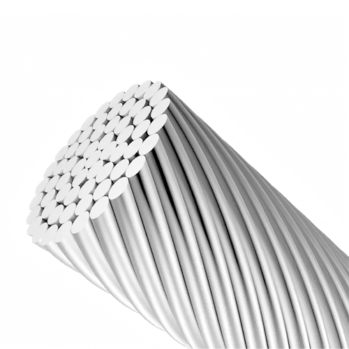
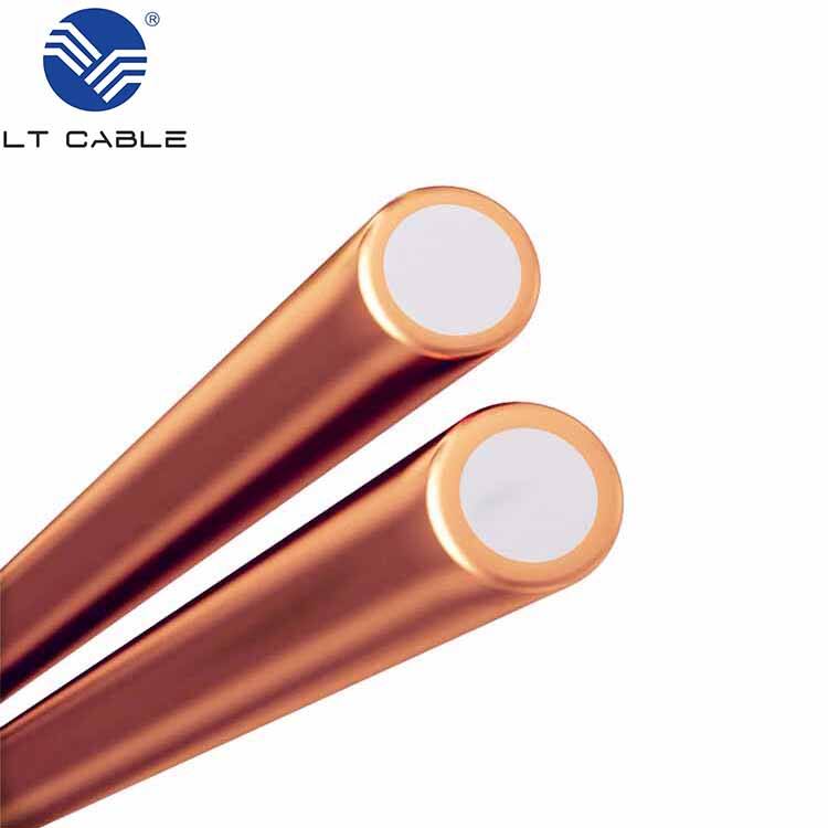
Differences Between Enameled Copper Wire and Copper Clad Aluminum

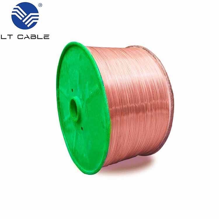
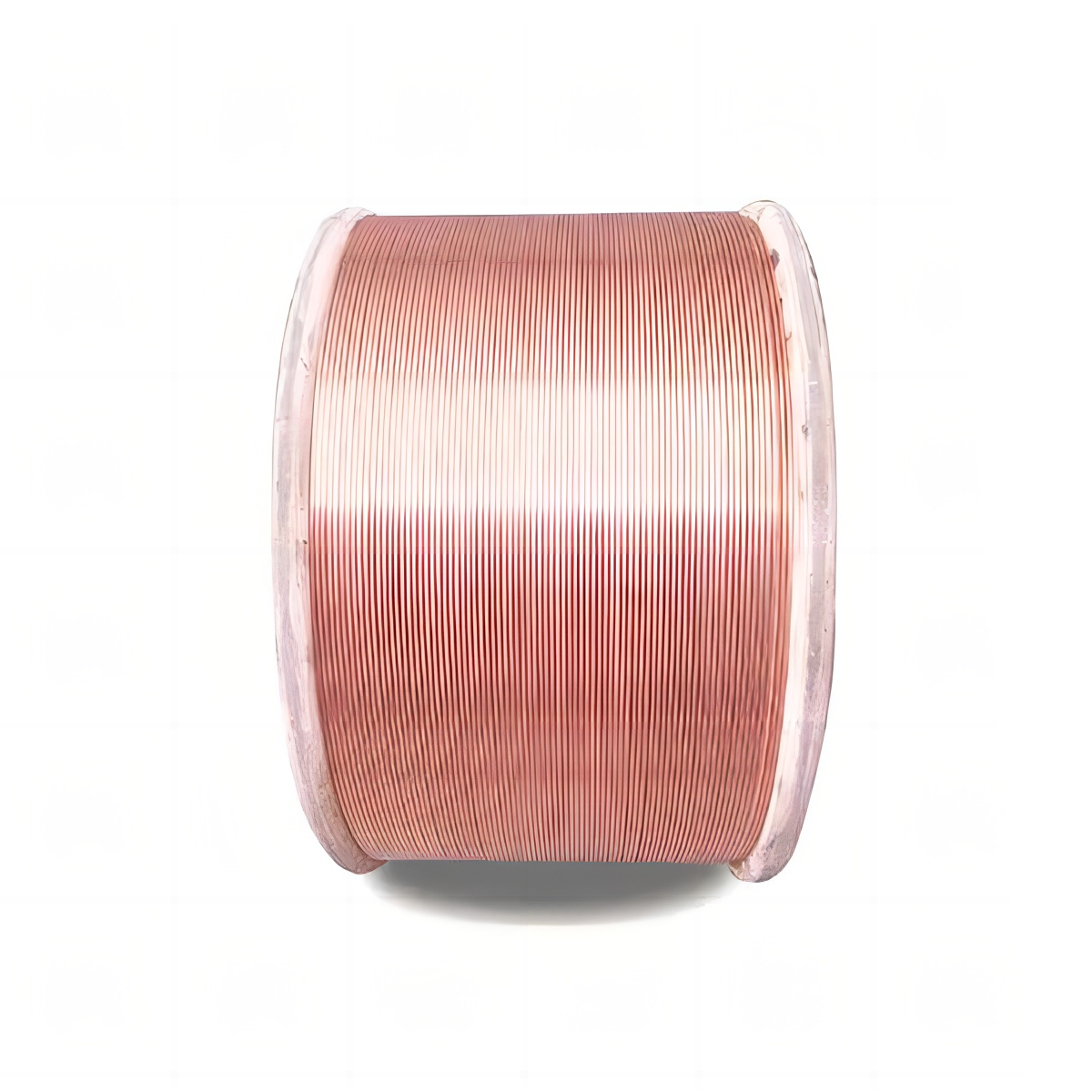
The conductivity of enameled copper wires stands out compared to other options, which is why they work so well in transformer and inductor applications where performance matters most. Their ability to conduct electricity efficiently helps keep systems running at peak levels without wasting power. When looking at alternatives though, copper clad aluminum offers some distinct benefits. It weighs less than pure copper and generally costs less too, making it attractive for budget conscious installations or situations where every ounce counts. Many manufacturers turn to copper clad aluminum for basic wiring jobs when expenses need to stay under control. So while both materials have their place, engineers typically choose enameled copper when maximum efficiency is required, whereas copper clad aluminum finds its niche in applications where saving money and cutting down on weight takes priority over absolute electrical performance.

Why Stranded Wire Requires Special Handling Compared to Solid Wire

Stranded wire is basically just several small wires twisted together, giving it that bendy quality needed when things move around a lot. But there's a catch with these multi-strand setups because they tend to break or wear out faster if not handled right. Those tiny individual strands work great for places with vibrations or constant motion, but stripping them bare or connecting terminals without care can ruin everything. Good technique matters here folks, otherwise all that flexibility turns into frustration later on down the line. Solid wires don't give this hassle since they're stiff and straightforward to work with. Stranded ones though? They need extra attention to keep working properly over time, especially in installations where bending comes part and parcel with daily operations.

Temperature Tolerance Variations in Enamel Coatings

The temperature resistance of enamel coatings varies quite a bit between different wire types, which makes a real difference in how they perform under heat stress. Take common options like polyurethane, polyester, or polyamide-imide coatings each has its own thermal limits that matter a lot when working in hot environments. Knowing what those limits are helps pick the right material for the job so devices last longer without wires failing unexpectedly. Research shows that once wires start operating past their temperature ratings, failure rates jump noticeably, which underscores why matching enamel type to application conditions matters so much. Since heat buildup remains a problem across countless electrical systems, getting the enamel choice right from the start often means the difference between reliable operation and costly repairs down the road.

Essential Tools for Enameled Wire Maintenance

Selecting the Right Abrasives for Enamel Removal

Getting the right abrasives matters a lot when removing enamel because various methods and grit levels really affect results. Most folks reach for sandpaper or grinding brushes, each with different roughness levels suitable for particular jobs. The finer grit stuff works best on detailed work where mistakes could ruin what's underneath the coating. Picking abrasives means thinking about what kind of wire we're dealing with and what exactly needs done. Too aggressive and we risk stripping away too much; too gentle and progress grinds to a halt. Take thin gauge wires for example they often call for super fine abrasives just to get the job done without wrecking their performance characteristics. Thicker wires handle rougher materials better since there's more material to spare during the process.

Importance of Temperature-Controlled Soldering Irons

A good temperature controlled soldering iron makes all the difference when working with enameled wire. Without proper temperature management, the heat can easily melt away that protective enamel layer, leaving the wire vulnerable to damage over time. Keeping things at just the right temp really matters because different wires react differently during soldering processes. Some folks swear by the Hakko FX-888D model since it lets them tweak temperatures down to the exact degree needed for whatever job they're tackling. Getting the combination right between the soldering iron model and actual temperature settings isn't just about making connections stick better. It actually extends how long those wires will last before needing replacement, saving money in the long run while ensuring reliable electrical connections every time.

Using Flux: Types and Application Methods

Flux is really important when working with enameled wire during soldering because it helps create stronger electrical connections and stops oxidation from happening. There are different kinds of flux out there, like rosin based stuff or water soluble options, each suited for particular jobs based on what needs to be achieved. For serious work where performance matters most, rosin based flux tends to work best. Water soluble varieties clean up much easier after soldering though, which makes them popular for certain applications. Getting the application right makes all the difference in getting good results without wasting materials. The trick is to apply just enough flux and watch how the solder flows across the surface. When done properly, this ensures good conductivity while keeping pesky residue buildup at bay. Most experienced technicians will tell you that going overboard with flux only creates more problems down the line.

Step-by-Step Guide to Soldering Enameled Wire

Proper Enamel Stripping Techniques Without Damaging Conductors

When stripping enamel off enameled wire without harming the actual conductor underneath, there are certain methods that work best while others should be avoided at all costs. Heat works pretty well for getting rid of that enamel coating, or sometimes people use special chemicals to dissolve it away. Either way, what matters most is making sure the wire stays conductive enough for good soldering later on. Don't go overboard with scraping though because that tends to damage the wire itself. Most pros stick to applying controlled amounts of heat or rely on those specialty chemicals recommended by manufacturers. These approaches protect the wire during the process and ultimately lead to better solder joints down the road when working on electronic projects.

Tinning Process for Optimal Electrical Contact

Tinning makes all the difference when it comes to getting good electrical contacts from enameled wires. The process basically coats the wire with a thin layer of solder, creating that smooth surface needed for proper conductivity while cutting down on resistance. How well this works depends heavily on the technique used. Some folks swear by heat strippable enamel because it just works better for certain applications than others. Industry data backs this up too many poorly tinned connections end up failing much more often than those done right. For anyone working with these wires, taking time to get the tinning right isn't just recommended its absolutely necessary if we want our electrical connections to hold up over time.

Creating Durable Connections: Heat Management Strategies

Controlling heat when soldering makes all the difference between good connections and damaged enamel coatings. Techs often rely on heat sinks or tweak their timing techniques to get better results from solder joints. Keep an eye on temps at all times really matters because too much heat will melt away those protective enamel layers over time. Most experienced焊工 know this stuff firsthand after seeing what happens when things get too hot. Proper temperature control isn't just theory it works in real world situations across different industries, making sure soldered components last longer and perform reliably day after day.

Preventive Maintenance and Damage Inspection

Identifying Early Signs of Enamel Degradation

Spotting early warning signs like discoloration, flaking, or cracks in enamel coatings matters a lot when it comes to keeping wires performing properly. When these issues appear, they usually mean the wire isn't conducting electricity as well as it should be. Checking regularly helps catch problems before they turn into big headaches that stop everything from working right. Research into how long wires last shows that sticking to regular checkups makes all the difference for keeping things running smoothly. Most professionals suggest planning out when inspections happen depending on how hard the equipment works and what kind of environment it sits in. Some facilities find monthly checks work best while others might need weekly looks if conditions get really tough on their wiring systems.

Testing Continuity in Stranded vs Solid Wire Configurations

When checking if wires are continuous in electrical systems, technicians typically grab a multimeter to see if current flows properly through the circuit. However, what works for one type of wire doesn't always work for another. Stranded wire, made up of many thin strands twisted together, needs special attention during testing because it bends easily and has gaps between strands that can fool standard tests. Solid wire is much simpler since it's just one thick conductor without those complications. Field reports show plenty of problems caused by people not adjusting their testing method based on wire type. We've seen installations fail repeatedly simply because someone used the wrong technique on stranded conductors. That's why experienced electricians develop specific routines for each wire configuration they encounter. Getting this right isn't just about following procedures it literally means the difference between safe operation and potential hazards down the line.

Moisture Protection and Corrosion Prevention

Keeping enameled wire safe from moisture and corrosion should be a top priority if we want to maintain its quality and how well it works over time. The best way to do this? Apply proper sealants and store the wire where humidity isn't an issue. Good materials matter too, especially when dealing with harsh weather conditions that just wear down wiring systems faster than normal. We've seen plenty of instances in the field where wires exposed to damp environments started showing signs of damage much sooner than expected. This real world evidence shows why taking basic precautions makes all the difference in protecting our investments against those pesky environmental factors that nobody wants to deal with.

Troubleshooting Common Enameled Wire Issues

Repairing Partial Discharge Damage in High-Voltage Applications

Partial discharge damage remains a major concern for anyone working with high voltage systems. The problem usually starts when there are tiny voids, cracks, or impurities hidden inside the insulation material. What happens next? Those little discharges start eating away at the enameled wire over time, which eventually leads to insulation breakdown and system failure if left unchecked. When it comes to fixing this kind of damage, technicians typically resort to patching and recoating procedures. Let's break down how it works in practice: locate the affected section first, give it a thorough cleaning, and then apply either specialized enamel or insulating varnish to bring back the wire's structural integrity. Field engineers who have dealt with hundreds of these repairs will tell you that following these steps makes all the difference. Most report success rates well above 80% in extending wire life expectancy while keeping electrical systems running reliably under stress conditions.

Addressing Insulation Resistance Failures

When insulation resistance fails in enameled wires, it usually happens because of things like overheating, mechanical stress, or exposure to corrosive substances over time. The results can be pretty serious too – think reduced performance across the board or even total system failure. For anyone dealing with these problems regularly, having a good troubleshooting strategy matters a lot. Most technicians swear by regular testing routines using specialized equipment like insulation resistance meters to get to the bottom of what's going wrong. Looking at actual field reports shows that following this methodical process cuts down on unexpected problems while making operations safer overall. This kind of proactive maintenance just makes sense for keeping electrical infrastructure running smoothly year after year.

Salvaging Overheated Windings: When to Recoat vs Replace

The choice between recoating or replacing overheated windings needs some serious thinking. Recoating works best for minor issues where only the surface enamel shows signs of wear without much degradation. But if the damage goes deeper and starts messing with the core structure itself, then replacement becomes unavoidable. Thermal damage levels and budget constraints are two big factors that influence what gets done. Industry pros suggest checking winding condition against established standards while also looking at how different options affect future performance costs. Most maintenance teams find it pays off to invest time upfront assessing these variables rather than rushing into quick fixes that might cause bigger problems down the road.

Best Practices for Long-Term Storage

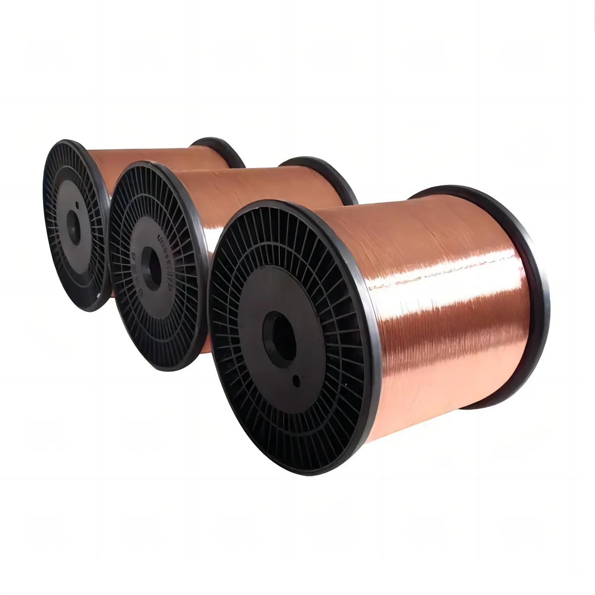
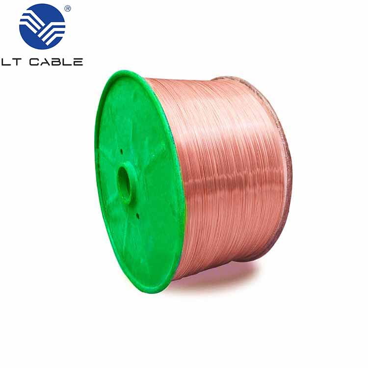
Environmental Controls for Bulk Wire Spools

Getting the environmental conditions right matters a lot when storing bulk wire spools for any length of time. The main things to watch are keeping temperatures steady, not letting humidity get too high, and making sure there's no direct light hitting the spools. When stored properly, enameled wire stays in good condition longer and keeps performing as expected. Research shows that if temperatures swing around too much, it actually changes both how the wire feels and what happens chemically inside, which could mess up how reliable it is later on. For best results, aim to keep temps somewhere between about 22°C and 30°C, and don't let humidity creep above 60%. Also worth noting that sunlight or even regular office lighting can slowly break down the insulation coating on those wires, leading to failures before their time. Companies that take care to control these factors tend to find their wire stock lasts much longer without issues, saving money and headaches down the road.

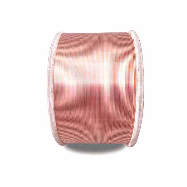
Anti-Oxidation Treatments for Copper Conductors

Anti oxidation treatments offer a smart way to make copper conductors last longer before they need replacing. People often use things like tinning, plating, or apply antioxidant oils and greases to cut down on oxidation issues. When we talk about tinning specifically, it means putting a thin coat of tin onto the copper surface. This creates a shield against both oxygen and moisture getting at the metal underneath. Experience shows this works really well at stopping corrosion while keeping the electrical properties intact. Most folks apply these coatings through simple methods like dipping components into solution or using electroplating techniques to get an even coverage across all surfaces. Maintenance matters too though. Checking regularly and touching up those protective layers when needed keeps everything working properly over time. Research from various long term tests indicates that copper wires treated with these anti oxidation approaches tend to stay functional much longer than untreated ones, meaning fewer replacements and lower costs overall for most industrial applications.

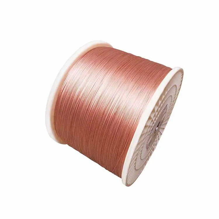
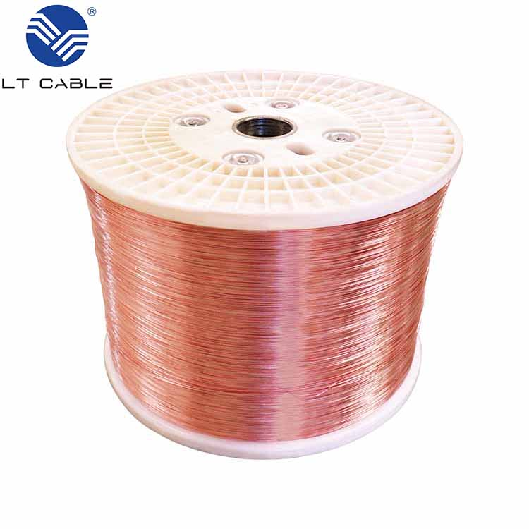
Proper Coiling Methods to Prevent Mechanical Stress

Getting the coiling right for enameled wires matters a lot if we want to avoid mechanical stress that could mess up how they perform. Most folks in the field will tell you to steer clear of tight coils and keep things even when winding them up. This helps stop the wire from getting bent out of shape or stretched too far, both of which can crack that protective enamel layer and lead to all sorts of problems down the line. We've seen plenty of cases where bad coiling practices, like those awkward reverse bends or pulling too hard, actually break the wire and make it less flexible over time. The trick is to use proper spools and guides that help maintain just the right angle while winding. This simple step cuts down on most of the common issues. Industry pros consistently point out that sticking to standard coiling procedures does more than just protect the wire itself it extends how long it lasts and makes whole systems run better. For companies investing in enameled wire products, getting this right means saving money in the long run and keeping operations running smoothly without unexpected breakdowns.

Advanced Techniques for Specialty Applications

Maintaining Enamel Integrity in High-Frequency Transformers

Keeping enamel intact on high frequency transformers matters a lot because these components face special problems from their operating environment. When those fast moving signals interact with the enamel coating, things start breaking down over time unless we handle it right. That means picking good materials upfront and sticking to proper maintenance routines. What happens physically isn't simple at all electrodynamic forces get involved that put real strain on the enamel layer, messing with its ability to insulate properly. Research published in the Journal of Applied Physics back in 2022 found that when enamel isn't applied consistently across transformer surfaces, efficiency drops off significantly. Industry experts recommend going for tougher enamel options or investing in better application techniques to avoid these issues. Newer studies keep pointing toward specialized enamel formulas designed specifically for harsh environments. These advancements help maintain performance standards while extending how long transformers last before needing replacement.

UV Resistance Considerations for Outdoor Installations

When installing equipment outdoors, UV resistance matters a lot for how well things perform over time. Sunlight breaks down enamel on wires pretty quickly, which leads to insulation problems and higher repair bills down the road. Picking the right materials and coatings makes all the difference here. According to findings published in the Solar Energy Journal, special coatings mixed with UV protection ingredients really extend product lifespan, helping systems hold up against tough weather conditions. We've seen this work in practice too. Solar farms across the country report their equipment lasts much longer when they use these UV resistant materials. Same goes for telecom towers standing in direct sunlight day after day. Companies save money on replacements and spend less time fixing broken components. For anyone working with outdoor electrical installations, investing in quality UV protected wiring isn't just smart it's practically essential if we want our infrastructure to last through those brutal summer months without constant headaches and unexpected costs.

Handling Litz Wire and Multi-Strand Configurations

Litz wire is known for cutting down on skin effect issues and works much better than regular wire in radio frequency applications, which gives it some serious benefits in certain situations. Basically made up of lots of tiny insulated strands twisted together, this special wire cuts energy loss and spreads out the electrical current more evenly across all those strands. When working with Litz wire during soldering jobs, technicians should really focus on keeping those twists tight and consistent throughout the whole length while being careful not to damage any individual strands when stripping insulation off. Most seasoned electricians will tell anyone who asks that following proper handling protocols matters a lot because messing up even just one part can ruin what makes Litz so good at what it does. We see Litz wire performing exceptionally well in things like high frequency transformers used in power supplies and induction heating units found in industrial kitchens. The difference in performance between Litz and standard copper wire becomes pretty obvious after running tests side by side. Real world experience shows that getting the installation right from start to finish makes all the difference in how reliable these systems actually are over time.

View More
How to Choose CCA Wire for Power Cables and Conductors

25

Dec

How to Choose CCA Wire for Power Cables and Conductors

What Is CCA Wire? Composition, Electrical Performance, and Key Trade-Offs

What Is CCA Wire? Composition, Electrical Performance, and Key Trade-Offs

Copper-clad aluminum structure: Layer thickness, bonding integrity, and IACS conductivity (60␗70% of pure copper)

Copper Clad Aluminum or CCA wire basically has an aluminum center covered with a thin copper coating that makes up around 10 to 15 percent of the overall cross section. The idea behind this combination is simple really it tries to get the best of both worlds lightweight and affordable aluminum plus the good conductivity properties of copper on the surface. But there's a catch. If the bond between these metals isn't strong enough, tiny gaps can form at the interface. These gaps tend to oxidize over time and can boost electrical resistance by as much as 55% compared to regular copper wires. When looking at actual performance numbers, CCA typically reaches about 60 to 70% of what's called the International Annealed Copper Standard for conductivity because aluminum just doesn't conduct electricity as well as copper does throughout its entire volume. Because of this lower conductivity, engineers need to use thicker wires when working with CCA to handle the same amount of current as copper would. This requirement pretty much cancels out most of the weight and material cost benefits that made CCA attractive in the first place.

Thermal limitations: Resistive heating, ampacity derating, and impact on continuous load capacity

The increased resistance of CCA leads to more significant Joule heating when carrying electrical loads. When ambient temperatures reach around 30 degrees Celsius, the National Electrical Code requires reducing the current capacity of these conductors by approximately 15 to 20 percent compared to similar copper wires. This adjustment helps prevent insulation and connection points from overheating beyond safe limits. For regular branch circuits, this means about a quarter to third less continuous load capacity available for actual use. If systems run consistently above 70% of their maximum rating, the aluminum tends to soften through a process called annealing. This weakening affects the conductor's core strength and can damage connections at terminations. The problem gets worse in tight spaces where heat simply cannot escape properly. As these materials degrade over months and years, they create dangerous hot spots throughout installations, which ultimately threatens both safety standards and reliable performance in electrical systems.

Where CCA Wire Falls Short in Power Applications

POE deployments: Voltage drop, thermal runaway, and non-compliance with IEEE 802.3bt Class 5/6 power delivery

CCA wire just doesn't work well with today's Power over Ethernet (PoE) systems, especially those following the IEEE 802.3bt standards for Classes 5 and 6 that can deliver up to 90 watts. The problem comes down to resistance levels that are about 55 to 60 percent higher than what we need. This creates serious voltage drops along regular cable lengths, making it impossible to maintain the stable 48-57 volts DC needed at devices on the other end. What happens next is pretty bad too. The extra resistance generates heat, which makes things worse because hotter cables resist even more, creating this vicious cycle where temperatures keep climbing dangerously high. These issues run afoul of NEC Article 800 safety rules as well as the IEEE specifications. Equipment might stop working altogether, important data could get corrupted, or worst case scenario, components suffer permanent damage when they don't receive enough power.

Long runs and high-current circuits: Exceeding NEC 3% voltage drop threshold and Article 310.15(B)(1) ampacity derating requirements

Cable runs longer than 50 meters often push CCA past the NEC's 3% voltage drop limit for branch circuits. This creates problems like inefficient equipment operation, early failures in sensitive electronics, and all sorts of performance issues. At current levels above 10 amps, CCA needs serious ampacity reductions according to NEC 310.15(B)(1). Why? Because aluminum just doesn't handle heat as well as copper does. Its melting point is around 660 degrees Celsius compared to copper's much higher 1085 degrees. Trying to fix this by oversizing the conductors basically cancels out any cost savings from using CCA in the first place. Real world data tells another story too. Installations with CCA tend to have about 40% more thermal stress incidents compared to regular copper wiring. And when these stress events happen inside tight conduit spaces, they create a real fire hazard that nobody wants.

Safety and Compliance Risks of Misapplied CCA Wire

Oxidation at terminations, cold flow under pressure, and NEC 110.14(A) connection reliability failures

When the aluminum core inside CCA wire gets exposed at connection points, it starts oxidizing pretty quickly. This creates a layer of aluminum oxide that has high resistance and can raise localized temperatures by around 30%. What happens next is even worse for reliability issues. When those terminal screws apply constant pressure over time, the aluminum actually flows out cold from the contact areas, making connections gradually loosen. This violates code requirements like NEC 110.14(A) that specify secure, low resistance joints for permanent installations. The heat generated through this process leads to arc faults and breaks down insulation materials, something we see frequently mentioned in NFPA 921 investigations about fire causes. For circuits handling more than 20 amps, problems with CCA wires show up about five times quicker compared to regular copper wiring. And here's what makes it dangerous - these failures often develop silently, giving no obvious signs during normal inspections until serious damage occurs.

Key failure mechanisms include:

  • Galvanic corrosion at copper␗aluminum interfaces
  • Creep deformation under sustained pressure
  • Increased contact resistance, rising over 25% after repeated thermal cycling

Proper mitigation requires antioxidant compounds and torque-controlled terminals specifically listed for aluminum conductors␔measures rarely applied in practice with CCA wire.

How to Select CCA Wire Responsibly: Application Fit, Certifications, and Total Cost Analysis

Valid use cases: Control wiring, transformers, and low-power auxiliary circuits ␔ not branch circuit conductors

CCA wire can be used responsibly in low-power, low-current applications where thermal and voltage-drop constraints are minimal. These include:

  • Control wiring for relays, sensors, and PLC I/O
  • Transformer secondary windings
  • Auxiliary circuits operating below 20A and 30% continuous load

CCA wiring shouldn't go into circuits that power outlets, lights, or any standard electrical loads around the building. The National Electrical Code, specifically Article 310, bans its use in 15 to 20 amp circuits because there have been real issues with things getting too hot, voltage fluctuations, and connections failing over time. When it comes to situations where CCA is allowed, engineers need to check that the voltage doesn't drop more than 3% along the line. They also have to make sure all connections meet the standards laid out in NEC 110.14(A). These specs are pretty tough to hit without special equipment and proper installation techniques most contractors aren't familiar with.

Certification verification: UL 44, UL 83, and CSA C22.2 No. 77 ␔ why listing matters more than labeling

Third-party certification is essential␔not optional␔for any CCA conductor. Always verify active listing against recognized standards:

Standard Scope Critical Test
UL 44 Thermoset-insulated wire Flame resistance, dielectric strength
UL 83 Thermoplastic-insulated wire Deformation resistance at 121°C
CSA C22.2 No. 77 Thermoplastic-insulated conductors Cold bend, tensile strength

Listing in the UL Online Certifications Directory confirms independent validation␔unlike unverified manufacturer labels. Non-listed CCA fails ASTM B566 adhesion testing seven times more frequently than certified product, directly increasing oxidation risk at terminations. Before specifying or installing, confirm the exact certification number matches an active, published listing.

View More
CCA Wire Specifications Guide: Diameter, Copper Ratio, and Tolerance

25

Dec

CCA Wire Specifications Guide: Diameter, Copper Ratio, and Tolerance

Understanding CCA Wire Composition: Copper Ratio and Core–Clad Architecture

Understanding CCA Wire Composition: Copper Ratio and Core–Clad Architecture

How Aluminum Core and Copper Cladding Work Together for Balanced Performance

Copper Clad Aluminum (CCA) wire combines aluminum and copper in a layered construction that manages to strike a good balance between performance, weight, and price. The inner part made from aluminum gives the wire strength without adding much weight, actually cutting down on mass by around 60% compared to regular copper wires. Meanwhile, the copper coating on the outside handles the important job of conducting signals properly. What makes this work so well is that copper conducts electricity better right at the surface where most high frequency signals travel because of something called the skin effect. The aluminum inside takes care of moving the bulk of the current but costs less money to produce. In practice, these wires end up performing about 80 to 90% as well as solid copper when it matters most for signal quality. That's why many industries still choose CCA for things like network cables, car wiring systems, and other situations where either money or weight becomes a real concern.

Standard Copper Ratios (10%–15%) – Trade-offs Between Conductivity, Weight, and Cost

The way manufacturers set copper to aluminum ratios in CCA wire really depends on what they need for specific applications. When wires have about 10% copper coating, companies save money since these are roughly 40 to 45 percent less expensive than solid copper options, plus they weigh around 25 to 30 percent less. But there's a tradeoff here too because this lower copper content actually makes the DC resistance go up. Take a 12 AWG CCA wire with 10% copper for instance it shows about 22% more resistance compared to pure copper versions. On the flip side, increasing the copper ratio to around 15% gives better conductivity, getting close to 85% of what pure copper offers, and makes connections more reliable when terminating. However, this comes at a cost since the savings drop to about 30 to 35% on price and only 15 to 20% in weight reduction. Another thing worth noting is that thinner copper layers create problems during installation, especially when crimping or bending the wire. The risk of the copper layer peeling off becomes real, which can mess up the electrical connection completely. So when choosing between different options, engineers have to balance how well the wire conducts electricity against how easy it is to work with during installation and what happens over time, not just looking at upfront costs alone.

Dimensional Specifications of CCA Wire: Diameter, Gauge, and Tolerance Control

AWG-to-Diameter Mapping (12 AWG to 24 AWG) and Its Impact on Installation and Termination

American Wire Gauge (AWG) governs CCA wire dimensions, with lower gauge numbers indicating larger diameters—and correspondingly greater mechanical robustness and current capacity. Precise diameter control is essential across the range:

AWG Nominal Diameter (mm) Installation Consideration
12 2.05 Requires wider bend radii in conduit runs; resists pull-through damage
18 1.02 Prone to kinking if improperly handled during cable pulls
24 0.51 Demands precision termination tools to avoid insulation breach or conductor deformation

Mismatched ferrule sizing remains a leading cause of field failures—industry data attributes 23% of connector-related issues to gauge-terminal incompatibility. Proper tooling and installer training are non-negotiable for reliable terminations, especially in dense or vibration-prone environments.

Manufacturing Tolerances: Why ±0.005 mm Precision Matters for Connector Compatibility

Getting the dimensions just right matters a lot for how well CCA wire works. We're talking about keeping things within a tight ±0.005 mm diameter range. When manufacturers miss this mark, problems happen fast. If the conductor ends up too big, it squishes or bends the copper coating when plugged in, which can boost contact resistance by as much as 15%. On the flip side, wires that are too small don't touch properly, leading to sparks during temperature changes or sudden power spikes. Take automotive splice connectors as an example they need no more than 0.35% diameter variation across their length to keep those important IP67 environmental seals intact while standing up to road vibrations. Achieving such exact measurements requires special bonding techniques and careful grinding after drawing. These processes aren't just about meeting ASTM standards either manufacturers know from experience that these specs translate into actual performance gains in vehicles and factory equipment where reliability counts most.

Standards Compliance and Real-World Tolerance Requirements for CCA Wire

The ASTM B566/B566M standard sets the foundation for quality control in CCA wire manufacturing. It outlines acceptable copper clad percentages usually between 10% and 15%, specifies how strong the metal bonds need to be, and establishes tight dimensional limits around plus or minus 0.005 millimeters. These specs matter because they help maintain reliable connections over time, especially important when wires face constant movement or temperature changes as seen in car electrical systems or power over Ethernet setups. Industry certifications from UL and IEC test wires under harsh conditions like rapid aging tests, extreme heat cycles, and overload scenarios. The RoHS regulations meanwhile make sure manufacturers aren't using dangerous chemicals in their production processes. Strict adherence to these standards isn't just good practice it's absolutely necessary if companies want their CCA products to perform safely, reduce the risk of sparks at connection points, and keep signals clear in critical applications where both data transmission and power supply depend on consistent performance.

Performance Implications of CCA Wire Specifications on Electrical Behavior

Resistance, Skin Effect, and Ampacity: Why 14 AWG CCA Carries Only ~65% of Pure Copper’s Current

The composite nature of CCA wires really puts a damper on their electrical performance, particularly when dealing with DC current or low frequency applications. While the outer copper layer does help reduce skin effect losses at higher frequencies, the inner aluminum core has about 55% more resistance compared to copper, which ends up being the main factor affecting DC resistance. Looking at actual numbers, 14 AWG CCA can only handle around two thirds of what pure copper wire of the same gauge would manage. We see this limitation showing up in several important areas:

  • Heat generation: Elevated resistance accelerates Joule heating, reducing thermal headroom and necessitating derating in enclosed or bundled installations
  • Voltage drop: Increased impedance causes >40% greater power loss over distance compared to copper—critical in PoE, LED lighting, or long-run data links
  • Safety margins: Lower thermal tolerance raises fire risk if installed without accounting for reduced current capacity

Uncompensated substitution of CCA for copper in high-power or safety-critical applications violates NEC guidelines and compromises system integrity. Successful deployment requires either upsizing the gauge (e.g., using 12 AWG CCA where 14 AWG copper was specified) or enforcing strict load limitations—both grounded in verified engineering data, not assumptions.

FAQ

What is Copper Clad Aluminum (CCA) wire?

CCA wire is a composite type of wire that combines an inner aluminum core with an outer copper cladding, allowing for a lighter yet cost-effective solution with decent electrical conductivity.

Why is the copper to aluminum ratio important in CCA wires?

The copper to aluminum ratio in CCA wires determines their conductivity, cost-efficiency, and weight. Lower copper ratios are more cost-effective but increase DC resistance, whereas higher copper ratios offer better conductivity and reliability at higher costs.

How does the American Wire Gauge (AWG) affect CCA wire specifications?

AWG impacts the diameter and mechanical properties of CCA wires. Larger diameters (lower AWG numbers) provide greater durability and current capacity, while precise diameter controls are crucial for maintaining device compatibility and proper installation.

What are the performance implications of using CCA wires?

CCA wires have higher resistance compared to pure copper wires, which can lead to more heat generation, voltage drops, and lower safety margins. They are less suitable for high-power applications unless appropriately upsized or derated.

View More

Customer Feedback on Our Copper Plated Aluminum Wire

John Smith
Exceptional Performance and Reliability

We switched to Litong Cable's copper plated aluminum wire for our solar projects, and the results have been outstanding! The wire's lightweight and corrosion resistance have significantly improved our installation efficiency.

Sarah Johnson
Highly Recommended for Automotive Applications

Using Litong Cable's copper plated aluminum wire in our electric vehicles has drastically improved performance. We’ve seen a noticeable increase in energy efficiency and overall vehicle performance.

Get a Free Quote

Our representative will contact you soon.
Email
Name
Company Name
Message
0/1000
Superior Conductivity and Lightweight Design

Superior Conductivity and Lightweight Design

Our copper plated aluminum wire is engineered to provide exceptional electrical conductivity while maintaining a lightweight profile. This combination is critical for industries where weight reduction is essential, such as aerospace and automotive. The copper plating enhances the wire’s performance, allowing for efficient energy transfer and reduced energy loss. This unique feature not only improves operational efficiency but also contributes to overall project cost savings by minimizing the need for additional support structures and materials.
Enhanced Durability for Harsh Environments

Enhanced Durability for Harsh Environments

The corrosion resistance of our copper plated aluminum wire makes it an ideal choice for applications exposed to harsh environmental conditions. Whether in coastal areas with high humidity or industrial settings with corrosive elements, our wire maintains its integrity and performance over time. This durability ensures a longer lifespan, reducing maintenance costs and the need for frequent replacements, which is a significant advantage for businesses looking to optimize their operational efficiency and reliability.
  • Product Consultation & Selection

    Product Consultation & Selection

    Tailored advice, perfect fit solutions.

  • Production & Supply Chain

    Production & Supply Chain

    Efficient manufacturing, seamless supply.

  • Quality Assurance & Certification

    Quality Assurance & Certification

    Rigorous testing, global certifications.

  • Post-Sales Support & Tech Help

    Post-Sales Support & Tech Help

    Prompt assistance, ongoing support.

Get a Free Quote

Our representative will contact you soon.
Name
Email
Mobile
Country/Region
Title
Message
0/1000