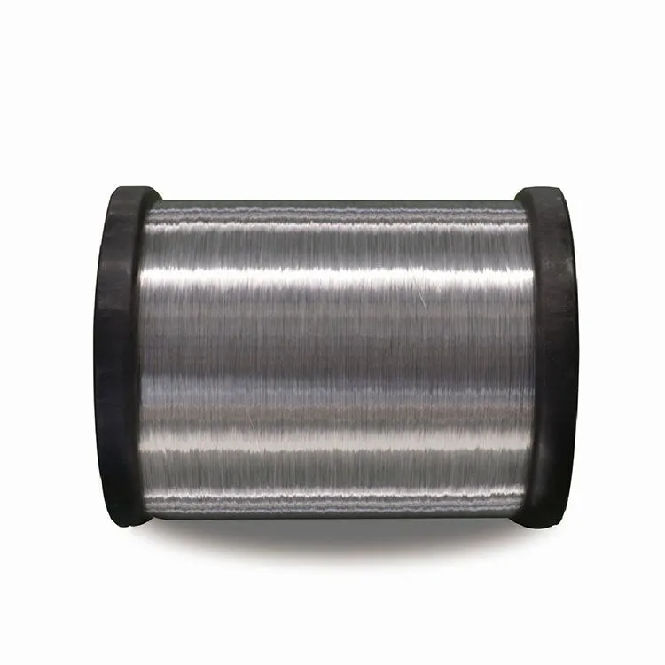
CCA Wire Quality Checklist: Copper Thickness, Adhesion, and Tests
Copper Cladding Thickness: Standards, Measurement, and Electrical Impact
ASTM B566 and IEC 61238 Compliance: Minimum Thickness Requirements for Reliable CCA Wire
The international standards out there actually set what counts as the minimum thickness for copper cladding on those CCA wires that need to perform well and stay safe. ASTM B566 says we need at least 10% copper volume, whereas IEC 61238 wants them to check the cross sections during manufacturing just to be sure everything meets specs. These rules really stop people from cutting corners. Some studies back this up too. When the cladding gets below 0.025 mm thick, resistance goes up around 18%, according to a paper published in the Journal of Electrical Materials last year. And let's not forget about oxidation issues either. Poor quality cladding speeds up oxidation processes significantly, which means thermal runaways happen about 47% quicker when dealing with high current situations. That kind of performance degradation can cause serious problems down the line for electrical systems relying on these materials.
| Measurement Method | Accuracy | Field Deployment | Copper Volume Loss Detection |
|---|---|---|---|
| Cross-Sectional | ±0.001mm | Laboratory Only | All levels |
| Eddy Current | ±0.005mm | Portable Units | >0.3% deviations |
Eddy Current vs. Cross-Sectional Microscopy: Accuracy, Speed, and Field Applicability
Eddy current testing allows quick thickness checks right at the site, giving results within about 30 seconds. This makes it great for verifying things while installing equipment in the field. But when it comes to official certification, cross-sectional microscopy is still king. Microscopy can spot those tiny details like micro-scale thinning spots and interface problems that eddy current sensors just miss. Techs often turn to eddy current for fast yes/no answers on the spot, but manufacturers need the microscopy reports to check if whole batches are consistent. Some thermal cycling tests have shown that parts checked through microscopy last almost three times longer before their cladding fails, which really highlights why this method matters so much for making sure products are reliable long term.
How Sub-Standard Cladding (>0.8% Cu Volume Loss) Drives DC Resistance Unbalance and Signal Degradation
When copper volume drops below 0.8%, we start seeing a sharp increase in DC resistance imbalance. For every extra 0.1% loss in copper content, resistivity jumps somewhere between 3 to 5 percent according to findings from the IEEE Conductor Reliability Study. The resulting imbalance messes with signal quality in several ways at once. First comes current crowding right where copper meets aluminum. Then there are these hot spots forming locally that can get as high as 85 degrees Celsius. And finally, harmonic distortions creep in above the 1 MHz mark. These problems really add up in data transmission systems. Packet losses climb past 12% when systems run continuously under load, which is way higher than what the industry considers acceptable - typically around just 0.5%.
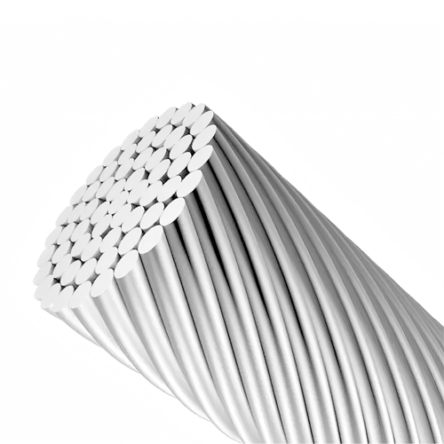
Copper–Aluminum Adhesion Integrity: Preventing Delamination in Real-World Installations
Root Causes: Oxidation, Rolling Defects, and Thermal Cycling Stress on the Bond Interface
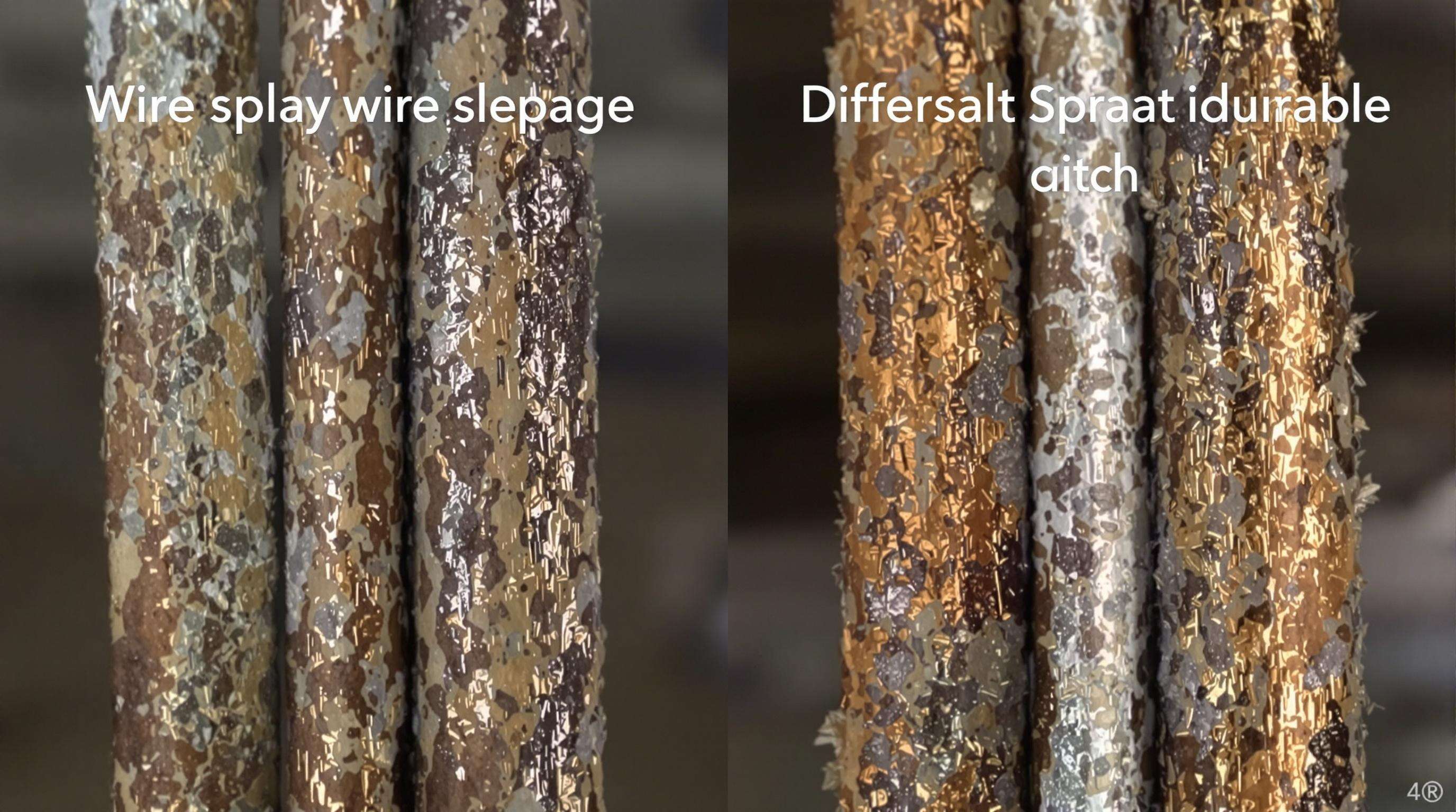
Delamination issues in copper clad aluminum (CCA) wire typically stem from several different problems. First off, when manufacturing happens, surface oxidation creates these non-conductive aluminum oxide layers on top of everything else. This basically weakens how well the materials stick together, sometimes cutting bond strength down by around 40%. Then there's what happens during rolling processes. Sometimes tiny voids form or pressure gets applied unevenly across the material. These little flaws become stress points where cracks start forming when any kind of mechanical force is applied. But probably the biggest issue comes from temperature changes over time. Aluminum and copper expand at very different rates when heated. Specifically, aluminum expands roughly half again as much as copper does. This difference creates shear stresses at their interface that can reach over 25 MPa. Real world tests show that even after only about 100 cycles between freezing temperatures (-20°C) and hot conditions (+85°C), the adhesion strength drops by about 30% in lower quality products. This becomes a serious concern for applications like solar farms and automotive systems where reliability matters most.
Validated Testing Protocols—Peel, Bend, and Thermal Cycling—for Consistent CCA Wire Adhesion
Good quality control really hinges on proper mechanical testing standards. Take the 90 degree peel test mentioned in ASTM D903 standards. This measures how strong the bond is between materials by looking at force applied across a certain width. Most certified CCA wires hit above 1.5 Newtons per millimeter during these tests. When it comes to bend testing, manufacturers wrap sample wires around mandrels at minus 15 degrees Celsius to see if they crack or separate at the interface points. Another key test involves thermal cycling where samples go through about 500 cycles from minus 40 to plus 105 degrees Celsius while being examined under infrared microscopes. This helps catch early signs of delamination that regular inspection might miss. All these different tests work together to prevent problems down the road. Wires that aren't properly bonded tend to show over 3% imbalance in their direct current resistance once they've been subjected to all that heat stress.
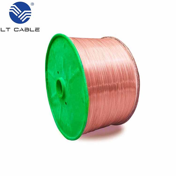
Field Identification of Genuine CCA Wire: Avoiding Counterfeits and Mislabeling
Visual, Scraping, and Density Checks to Differentiate True CCA Wire from Copper-Plated Aluminum
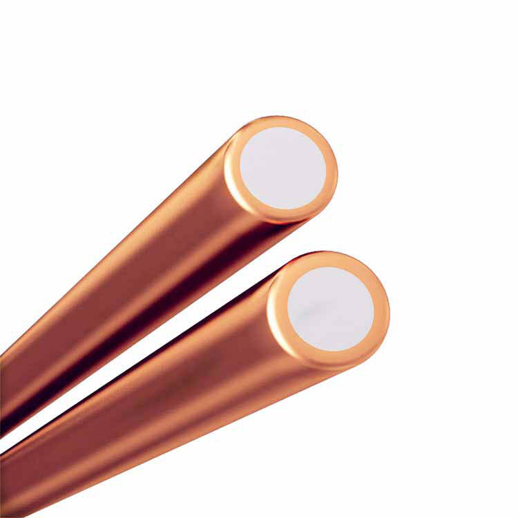
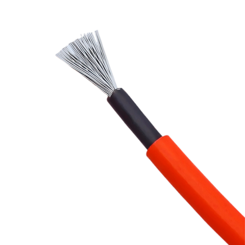
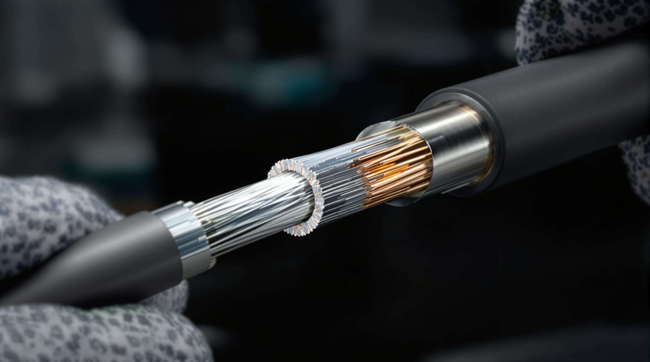
Real Copper-Clad Aluminum (CCA) wires have certain features that can be checked on site. To start with, look for the "CCA" marking right on the outside of the cable as specified in NEC Article 310.14. Counterfeit stuff usually skips this important detail entirely. Then try a simple scratch test. Strip back the insulation and gently rub the conductor surface. Authentic CCA should show a solid copper coating covering a shiny aluminum center. If it starts peeling, changes color, or reveals bare metal underneath, chances are good it's not genuine. Lastly, there's the weight factor. CCA cables are significantly lighter than regular copper ones because aluminum just isn't as dense (about 2.7 grams per cubic centimeter compared to copper's 8.9). Anyone working with these materials can feel the difference pretty quickly when holding similar sized pieces side by side.
Why Burn and Scratch Tests Are Unreliable—and What to Use Instead
Open-flame burn and aggressive scratch tests are scientifically unsound and physically damaging. Flame exposure oxidizes both metals indiscriminately, while scratching cannot assess metallurgical bond quality—only surface appearance. Instead, use validated nondestructive alternatives:
- Eddy current testing, which measures conductivity gradients without compromising insulation
- DC loop resistance verification using calibrated micro-ohmmeters, flagging deviations >5% per ASTM B193
-
Digital XRF analyzers, delivering rapid, non-invasive elemental composition confirmation
These methods reliably detect substandard conductors prone to resistance unbalance >0.8%, preventing voltage drop issues in communication and low-voltage circuits.
Electrical Verification: DC Resistance Unbalance as a Key Indicator of CCA Wire Quality
When there's too much DC resistance imbalance, it's basically the clearest sign something's wrong with CCA wire. Aluminum naturally has about 55% more resistance than copper does, so whenever the actual copper area gets reduced because of thin coatings or bad bonds between metals, we start seeing real differences in how each conductor performs. These differences mess up signals, waste power, and create serious problems for Power over Ethernet setups where small voltage losses can actually shut down devices completely. Standard visual inspections just don't cut it here. What matters most is measuring DC resistance imbalance according to those TIA-568 guidelines. Experience shows that when imbalance goes over 3%, things tend to go south fast in big current systems. That's why factories need to test this parameter thoroughly before shipping out any CCA wire. Doing so keeps equipment running smoothly, avoids dangerous situations, and saves everyone from having to deal with expensive fixes later on.