Light Weight Aluminum Conductor | AL-Mg Alloy Wire

Get a Free Quote

Our representative will contact you soon.
Name
Email
Mobile
Country/Region
Choose the product you want
Message
0/1000
The Superior Choice for Efficient Electrical Solutions

The Superior Choice for Efficient Electrical Solutions

Light weight aluminum conductors are designed for optimal performance while maintaining a low weight profile, making them ideal for various electrical applications. Their lightweight nature reduces installation costs and enhances handling efficiency, especially in overhead power lines and other applications where weight is a critical factor. The use of aluminum also offers excellent conductivity, ensuring minimal energy loss during transmission. With our commitment to quality, each conductor undergoes rigorous testing to meet international standards, ensuring reliability and durability. Our fully automated production lines guarantee precision in every step, from raw material selection to final product delivery, allowing us to meet diverse customer needs with customized solutions.
Get A Quote

Case Studies

Transforming Power Distribution in Urban Areas

In a recent project aimed at upgrading the urban power distribution network, our light weight aluminum conductors were selected for their superior performance and reduced installation complexity. The project involved replacing outdated copper lines with our aluminum conductors, resulting in a 30% reduction in installation time and significant cost savings for the municipality. The lightweight nature of the conductors allowed for easier handling and installation in densely populated areas, minimizing disruption to local communities. The enhanced conductivity of our aluminum conductors also improved energy efficiency, leading to reduced operational costs for the city.

Enhancing Renewable Energy Projects

A leading renewable energy company chose our light weight aluminum conductors for a large-scale solar power project. The project required efficient energy transmission from solar panels to the grid, and our conductors provided an ideal solution due to their low weight and high conductivity. The use of aluminum allowed for longer spans between poles, reducing the number of required installations and lowering overall material costs. The project successfully demonstrated how our products can support sustainable energy solutions while providing significant economic benefits.

Infrastructure Development in Remote Areas

In a challenging infrastructure project aimed at extending electrical services to remote communities, our light weight aluminum conductors played a crucial role. The reduced weight allowed for easier transportation and installation in rugged terrains, where traditional materials would have posed logistical challenges. Our conductors ensured reliable power delivery to underserved areas, improving the quality of life for residents. The project highlighted our commitment to providing tailored solutions that address specific customer needs while enhancing community development.

Related products

At Litong Cable, we take great pride in making quality lightweight conductors in bulk for our customers all around the world. It takes hard work and great dedication to develop the processes that will prove reliability and top quality performance to our customers. For every conductor, we start with the selection of top quality raw materials, and then, we will provide our materials thru our precision drawing and annealing processes in order to enhance the electrical traits of the aluminum. Our management team has designed fully automated production systems that allow us to have the highest level of quality and consistency with every batch. In today's world, we all have to work efficiently and we have to prove reliability. It is our mission to provide conductors that will go beyond the expectations of our customers. Our lightweight aluminum conductors will fit perfectly for applications that include power transmission, and urban infrastructures. When you choose Litong Cable, you partner with a company that hopes for the highest level of quality and innovation.

Frequently Asked Questions About Light Weight Aluminum Conductors

What are the advantages of using light weight aluminum conductors?

Light weight aluminum conductors offer several advantages, including reduced installation costs due to their lower weight, enhanced handling efficiency, and excellent electrical conductivity. They are ideal for overhead power lines and renewable energy projects, where minimizing weight can lead to significant logistical benefits.
While copper conductors have traditionally been used for electrical applications, aluminum conductors provide a lighter and cost-effective alternative. Our aluminum conductors offer comparable conductivity while reducing installation complexity and overall material costs, making them a preferred choice for many projects.

Related article

Wondering how photovoltaic wire is engineered to shine in solar energy systems? Let's dig deeper.

22

Feb

Wondering how photovoltaic wire is engineered to shine in solar energy systems? Let's dig deeper.

Understanding Photovoltaic Wire

PV wire has been developed specifically for transmitting electricity from solar panels while keeping energy losses to a minimum. Standard electrical cables just aren't cut out for what PV wires need to do. These special cables can take on tough outdoor environments without breaking down. They resist things like sunlight damage, water intrusion, and temperature extremes that would ruin regular wiring over time. For anyone running a solar setup, this kind of cable isn't optional it's absolutely necessary if the system is going to work properly day after day. The right PV cables improve safety margins too because they're constructed to manage those big power surges that happen when multiple panels generate electricity at once. Most installers will tell you that investing in quality PV wiring pays off handsomely in the long run since these cables keep working reliably through heat waves, cold snaps, and everything else Mother Nature throws at them.

Engineering of Photovoltaic Wire for Solar Energy Systems

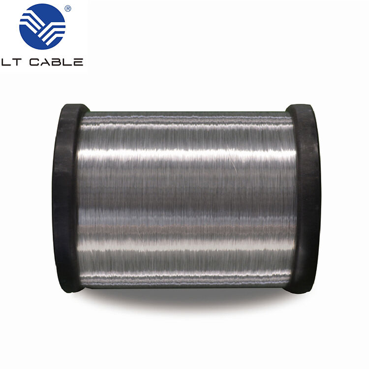
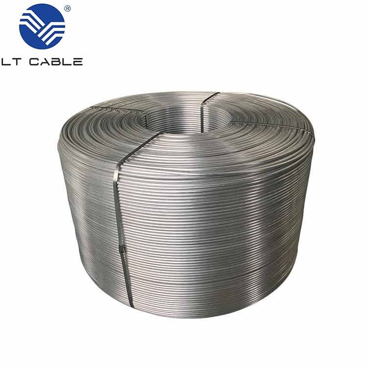
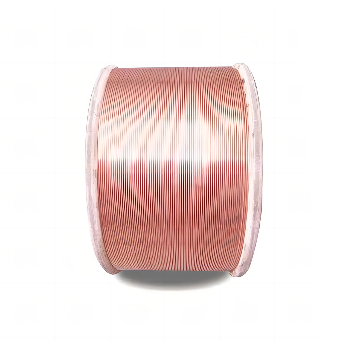
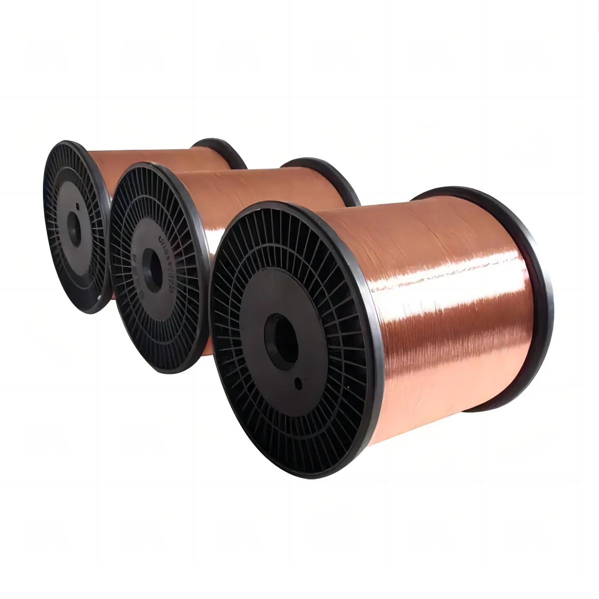
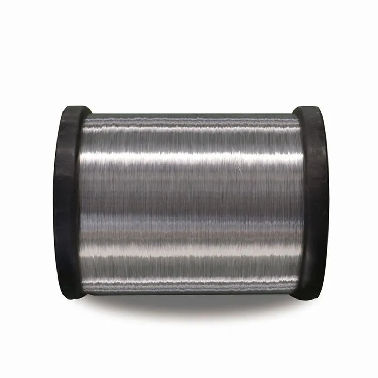
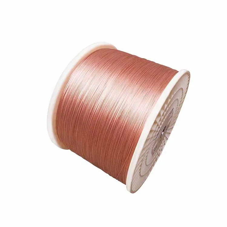
The performance and reliability of solar energy systems really depend on photovoltaic (PV) wiring. Most PV cables come in either copper or aluminum varieties, though copper generally gets the nod because it has less resistance and conducts electricity better than aluminum does. For top tier solar setups where every bit of power matters, copper remains the go to material since it cuts down on those annoying energy losses. But lately we've seen more solar installers opting for copper clad aluminum wire (CCA wire) instead. The CCA stuff gives decent conductivity at a fraction of the price, which explains why so many budget minded solar projects have started using it. This shift toward more affordable wiring options reflects what's happening across the industry as companies look for ways to cut costs without sacrificing too much performance when building out renewable energy infrastructure.

The insulation on PV wires matters a lot because it decides how well they can handle what Mother Nature throws at them. There are several options out there including PVC, PVDF, and XLPE, each offering varying degrees of protection against the elements. Take XLPE for example this stuff really stands up to heat and lasts longer than most alternatives. That's why many installers prefer it when working on projects across different climate zones or in tough conditions where wires face temperature swings day after day plus constant sun exposure. With the growth of solar power installations worldwide, picking the correct wire material paired with suitable insulation isn't just important anymore it's absolutely necessary if we want our panels to keep generating electricity safely for years to come without unexpected failures down the road.

Key Features of Photovoltaic Wire

PV wire stands out because it lasts so long, making it ideal for outdoor installations where replacement would be a hassle. Manufacturers put these cables through all sorts of stress tests they need to handle everything from scorching heatwaves to freezing winters, plus resist damage from chemicals and physical wear. This kind of toughness matters a lot when setting up solar panels since nobody wants their system failing after just a few years. The upfront cost might seem high, but most installers know that good quality wiring saves money down the road by avoiding premature replacements and maintenance headaches.

Following industry standards like UL 4703 matters a lot when talking about PV wire quality. These standards aren't just there for show either they actually guarantee those impressive voltage ratings we see, sometimes going above 600 volts. That kind of rating makes all the difference for keeping solar systems safe while they run at their best. When manufacturers stick to these tough requirements, they're basically putting up roadblocks against dangerous electrical problems that could happen otherwise. Plus, this attention to detail helps make sure solar panels work efficiently from day one. As more people turn to clean energy solutions, proper wiring becomes even more important in making sure everything runs smoothly without unexpected issues down the line.

Types of Photovoltaic Wire Explained

What makes photovoltaic wire so special? Well, it can handle much higher temperatures than regular wire and won't break down when exposed to UV rays from the sun. This matters a lot because normal wires would degrade after sitting outside for years. That's why PV wire works so well in outdoor installations where solar panels need to operate reliably day after day. Standard electrical wiring just isn't built for this kind of punishment. The manufacturers design PV wire specifically to stay intact even when baking in direct sunlight or dealing with extreme heat fluctuations common in many climates around the world.

Stranded wire stands out for its flexibility, which really matters when working in tight spots where stiff wires just won't fit. Installers appreciate this quality because it saves time and frustration during complex installations. Enameled wires take things further by adding those extra insulation layers that help prevent corrosion problems, especially important in damp locations like near water sources or underground conduits. When someone knows about these different options, they can pick what works best for their particular solar project setup while still meeting all the necessary code requirements from local authorities overseeing electrical work.

Being aware of these wire types and their applications is crucial for specialized solar installations. By aligning choices with specific requirements and adhering to industry guidelines, installers can optimize safety and performance in solar energy systems. Quality selection is essential to handle diverse installation conditions effectively.

Selecting the Right Photovoltaic Wire

Choosing the correct photovoltaic or PV wire makes all the difference when it comes to getting good results from solar panels without compromising safety. There are several things worth considering before making a purchase decision including where exactly the system will be installed, what kind of electrical load needs carrying through those wires, plus how well everything works together within the broader setup. Keep in mind that different situations call for different types of wiring materials too. For example outdoor installations require special grade PV cables built specifically to resist damage from sunlight exposure over time plus survive harsh weather extremes something standard household wiring simply isn't made for. Taking care of these details upfront pays off big time down the road by keeping things running smoothly and avoiding expensive breakdowns later on.

Looking at a stranded wire size chart helps pick the correct gauge when dealing with the amperage needs of solar panels. The right wire thickness matters because it needs to carry all that electricity safely without getting too hot, which protects both performance and lifespan of the whole system. Stranded wires bend easier than solid ones, so they work better in tight spots or awkward corners where solar equipment gets installed. Many installers find this extra flexibility makes a big difference during complicated roof mount jobs or when running cables through existing structures.

The solar industry keeps changing fast, so it makes sense to track what's happening with materials and wiring tech if we want better performance from our panels and longer lasting installations. New wires on the market now come with better insulation and stuff that conducts electricity more efficiently, which can really boost how well whole systems work together. Staying updated isn't just about having the latest gear either; it means installations stay relevant for years down the road instead of becoming obsolete when standards change or new tech comes along. Most installers know this already, but many still miss out on some pretty good improvements simply because they haven't checked what's available recently.

PV Wire Usage in Solar Installations

PV wire plays a vital role across all sorts of solar projects, whether someone has just a few panels on their roof or massive solar fields stretching for miles. What makes this wiring so good at handling everything from backyard installations to industrial parks? Well, it's built specifically to handle whatever Mother Nature throws at it. These wires can take extreme heat, cold snaps, and even lightning storms without breaking down. Plus they work safely with the high voltages needed for proper operation. When connecting panels to inverters and then feeding electricity into the main power grid, reliable PV wiring keeps things running smoothly day after day. Without quality connections throughout the system, we'd see drops in performance that nobody wants when relying on solar power for daily needs.

Installing photovoltaic wiring requires following local building regulations and electrical standards to keep things safe and legal. Make sure all those connections are properly sealed because water getting inside is a real problem that causes short circuits down the road. Don't forget about strain relief either. Without it, wires get damaged from constant movement and vibration, which eventually breaks down the whole system. Taking these steps doesn't just prolong equipment life either. Systems perform better when everything stays intact and functioning as intended without unexpected failures.

Getting the installation right means putting in good quality junction boxes and making sure everything is properly insulated. These things work together to make solar systems last longer and perform better over time. The junction boxes keep those important connection points safe from rain, dust, and other stuff that gets in there. Quality insulation does double duty too it stops electricity from leaking out and helps prevent fires. When installers take these precautions seriously, the whole system tends to stick around for years without needing constant fixes. This matters because nobody wants their solar panels going offline when they need power most. And let's face it, proper installation isn't just about avoiding problems down the road it actually makes a real difference in how much clean energy gets produced day after day.

View More
Why Twisted Wire is the Key to Stable Car Electrical Connections

22

Mar

Why Twisted Wire is the Key to Stable Car Electrical Connections

Understanding Twisted Wire Technology in Automotive Systems

Basic Structure: Twisted vs. Solid vs. Stranded Wire

In automotive systems, twisted, solid, and stranded wires all serve different purposes thanks to their unique structures. Take twisted wire for instance it usually has those enameled strands wrapped together. People love this type because it bends easily and cuts down on that annoying electromagnetic interference we all know as EMI. The way these strands twist around each other actually helps the wire handle bumps and shakes better while still working properly. Stranded wire works similarly but just has more individual strands bundled together, which makes it super flexible for getting into tight spots where space matters most. Solid wire takes a completely different approach with one big solid core inside. This gives it great conductivity and lasting power, so it's typically used in places where the wire won't be moved much after installation.

Twisted wire has one big plus point when it comes to fighting off electromagnetic interference. The way these wires are constructed actually cuts down on EMI pretty well, something that matters a lot in cars where there's plenty of high frequency noise floating around. Take enameled wire for instance. When manufacturers twist this type together, they get that protective enamel coating working overtime to prevent shorts. This kind of setup shows up all over the place in motor windings and other critical components inside electric motors. With modern vehicles relying so heavily on clean signal paths, knowing what separates twisted from straight wiring makes all the difference. Engineers spend hours debating which wire type works best for different parts of the vehicle because getting this right can mean smoother operation and fewer headaches down the road.

How Twisting Affects Electrical Signal Integrity

When wires are twisted together, it actually helps maintain better electrical signals, which matters a lot in car electronics where signal loss can be problematic. The main benefit comes from how this twisting works against electromagnetic interference. Basically, when current flows through parallel wires, they create magnetic fields that interfere with each other. But twist those wires just right and those fields start cancelling each other out instead. Research into cable design shows that increasing the number of twists along a given length makes this cancellation even more effective. Most automotive engineers will tell you that properly twisted cables can bring down EMI to almost nothing across their entire run, keeping data transmission clean and reliable throughout the vehicle's wiring system.

Twisting wires works mainly because it cancels out magnetic fields. Current running through these twisted pairs creates opposing magnetic fields in each half of the twist. The result? Much less interference from unwanted voltages and outside noise sources. Tests back this up consistently. Car manufacturers rely heavily on this technique since their vehicles operate in all sorts of electromagnetic environments. From engine compartments to passenger cabins, there's always background electrical noise competing with important signals. That's why properly twisted wiring remains so critical throughout modern cars' increasingly complicated electrical systems.

Key Benefits of Twisted Wire for Car Electrical Connections

EMI Reduction Through Magnetic Field Cancellation

Twisting wires remains a popular approach for cutting down on electromagnetic interference (EMI) problems inside cars and trucks. When wires get twisted together, they create opposing magnetic fields that basically cancel each other out. The result? Less unwanted electrical noise messing with sensitive equipment. Research indicates these twisted arrangements knock EMI levels way down compared to regular straight wires running parallel. Some tests even found reductions exceeding 70% in certain situations. Makes sense why automotive engineers love this trick so much. In modern vehicles packed full of electronic components, keeping those signals clean matters a lot. Safety systems need reliable connections after all, and twisted wiring helps ensure communication stays intact between different parts of the vehicle's complex network.

Enhanced Durability in High-Vibration Environments

Twisted wires tend to hold up really well over time, especially when used in cars that constantly vibrate and move around. What makes them special is how they're built - the twisting lets them bend without breaking as easily as regular solid or stranded wires would under the same rough treatment. Car makers have noticed this firsthand too. Some big names in the industry report their twisted wire connections stay intact much longer when subjected to those relentless vibrations we see in vehicles day after day. Stranded wires just don't cut it in these situations since they wear down faster, and solid ones? Well, they often just snap right off completely. For anyone looking at long term reliability in automotive wiring systems where shaking and rattling is basically part of the job description, twisted wires simply offer advantages that other types just cant match up to.

Improved Flexibility for Complex Routing

Twisted wire designs offer real advantages when it comes to routing through the cramped spaces inside modern vehicles. Solid wires and those made from copper clad aluminum just don't bend well enough for all those tight corners and awkward angles that come standard in today's car interiors. The twist gives these wires the flexibility needed to snake through engine compartments and dashboards where straight runs simply won't work. For mechanics and installers, this means fewer headaches during assembly and better integration with other components. Automotive engineers appreciate this too since they can create more advanced electrical layouts without constantly fighting against the limitations of traditional wiring options. Better installation times translate into cost savings on production lines, while also helping maintain the reliability and performance standards expected from modern vehicle electrical systems.

Twisted Wire vs. Solid and Stranded Conductors

Current Capacity Comparison: Twisted vs. Solid Wire

When it comes to cars, how much electricity twisted wire can carry makes all the difference compared to regular solid wire. The twisty design actually works better for moving current because of the way the strands are woven together, creating more surface area that helps get rid of heat faster. This matters a lot in car electrical systems where keeping things running smoothly without overheating is critical. Some research published in an engineering journal found that twisted wires handle about 15 percent more current than their solid counterparts. Most car makers follow guidelines from groups like the IEC when picking out wiring materials. These rules help them choose wires that won't overheat or fail under normal driving conditions, which keeps everyone safer on the road.

Flexibility Advantage Over Copper Clad Aluminum (CCA) Wire

When it comes to flexibility, twisted wire definitely outperforms copper clad aluminum (CCA) wire, particularly in those complicated vehicle layouts we see these days. Twisted wire just bends and twists right through all those tight spots in cars without snapping, while CCA might be lighter but tends to break down when things get really complicated. Take modern car designs where wires need to snake through engine compartments and under dashboards. Mechanics actually report faster installations with twisted wires since they don't kink up so easily. Most major car manufacturers now specify twisted wire for their production lines simply because these wires hold up better during assembly and after years of vibration from everyday driving conditions something every mechanic knows matters a lot in keeping vehicles running smoothly.

Why Stranded Wire Complements Twisted Pair Designs

In automotive wiring applications, stranded wire works alongside twisted wire designs to boost performance across different vehicle systems. When combined properly, these wires maintain good connections even when subjected to vibrations and temperature changes common in cars. We see this happening in critical areas like engine management controls where reliable signal transmission matters most. The automotive industry has noticed this trend too many manufacturers now prefer using mixed wiring approaches because they get better results from combining flexible stranded conductors with the structural benefits of twisted pairs. This practice helps meet strict performance requirements while keeping electrical systems running smoothly for longer periods without failures.

Practical Applications in Modern Vehicle Systems

Stable Sensor Data Transmission for ADAS

Twisted wire is really important for keeping data transmission stable in those Advanced Driver-Assistance Systems (ADAS) found in today's cars. When manufacturers twist the wires together, it cuts down on electromagnetic interference problems. This matters a lot now that cars have so many different electronic systems packed into them. Industry numbers show that when using twisted wiring instead of other approaches, data errors drop quite a bit, making these driver assistance features both safer and more dependable over time. Take Tesla for instance they actually implemented twisted pair wiring throughout their vehicle line-up. Their engineers noticed much better sensor communication between components, especially under real world driving conditions where all sorts of electrical signals are bouncing around inside the car.

Noise-Free Audio in Infotainment Systems

Twisted wire tech plays a big role in getting clean audio from car infotainment systems. These wires work really well against electromagnetic interference, something that causes those annoying noises drivers hear while on the road. Car audio specialists will tell anyone serious about sound quality that good wiring matters a lot, especially when we're talking about twisted pairs. Take the BMW 7 Series as an example. They actually use these special wires in their audio setup so people can enjoy music without all that background static messing things up during their drive. Most car owners probably don't think about this stuff, but it makes a real difference in how satisfying the whole listening experience feels inside the vehicle cabin.

Reliable Ignition and ECU Communication

Good wiring is absolutely necessary for proper functioning of ignition systems and those important computer parts called ECUs. We've seen plenty of cars on the road with bad wiring that just plain breaks down. Take some models from a few years back where people had all sorts of trouble starting their vehicles because the wires couldn't handle the job. Twisted wire stands out because it conducts electricity better and holds up longer under stress, which keeps those vital signals moving between parts without interruption. When manufacturers invest in quality wiring solutions, they're not just preventing breakdowns but actually making cars run smoother and last longer overall. The difference might seem small at first glance, but over time it adds up to fewer repairs and happier customers.

View More
How can a wire product solve the problem of signal interference?

14

Jul

How can a wire product solve the problem of signal interference?

Fundamentals of Signal Interference in Wiring

What Causes Signal Interference in Electrical Systems?

Most signal problems in electrical systems come from electromagnetic interference or EMI for short. Basically, outside electromagnetic fields mess with normal signal transmission. When this happens, signals get weaker and communication errors pop up all over the place, which makes electrical systems work less efficiently and reliably. A specific form of EMI called radio frequency interference creates special headaches because it really messes with communication signals, particularly bad in wireless setups. Poor grounding and not enough shielding inside equipment just makes these problems worse. Good grounding helps cut down on voltage differences that cause interference issues. Proper shielding blocks those pesky outside signals from getting in. That's why EMC standards matter so much in this field. These standards make sure different devices can coexist without messing each other up, something manufacturers take very seriously when designing new products.

Types of Interference: EMI vs RFI Explained

Getting clear on what separates EMI from RFI makes all the difference when dealing with signal problems. EMI basically messes with electronics everywhere, coming from things like lightning strikes (natural) or machines running nearby (artificial). If left unchecked, it can really throw sensitive equipment off track. Then there's RFI, which falls under the broader EMI category but specifically relates to radio waves. Think about how cell towers or Wi-Fi routers create this kind of interference. When technicians know whether they're facing EMI or RFI issues, they pick the right protective measures for cables and shielding materials. Standards bodies like CISPR and the FCC set limits on acceptable levels of both types of interference. Engineers follow these guidelines closely when building systems so everything works together without causing electromagnetic chaos.

Wire Types for Minimizing Signal Interference

Stranded Wire vs Solid Wire: Flexibility and Performance

Stranded wire is basically just lots of tiny wires twisted together, and this gives it way more flexibility than other types. That's why electricians love using it when they need to run cables around corners or through tight spaces. Think about those complicated home theater setups where wires have to snake through walls all over the place. On the flip side, solid wire comes as one big chunk of metal. It conducts electricity better because there's less resistance, but don't expect much bendiness from it. The downside? Those stiff wires can be real pain to work with in tricky installations. Still, they're pretty good for things like power lines or industrial equipment where the cable stays put most of the time without needing constant adjustment.

In situations where things get shaken around or moved frequently, most engineers go with stranded wire because it handles those conditions better without breaking down over time. When deciding between stranded versus solid wire, folks need to think about how easy it will be to install alongside what kind of electrical work needs doing. Solid wires might be simpler to run through walls but struggle when there's any flexing involved. Stranded offers flexibility at the cost of slightly different conductivity characteristics. Getting this right matters a lot for making sure wiring jobs last long term without causing headaches later on.

Advantages of Enameled Wire for EMI Reduction

Enameled wire has that thin coating which actually makes it pretty good at fighting off electromagnetic interference or EMI for short. Because of this property, it works really well in all sorts of delicate electronic setups where even small amounts of interference can cause problems. The best part? These wires take up much less room during installation compared to other options, yet they still keep signals clean and strong throughout their operation. A lot of studies have shown how useful these wires are specifically in motor designs and transformer constructions. They cut down on unwanted noise between components and generally make everything run smoother than standard alternatives would allow.

Different types of enamel coatings offer additional benefits, providing thermal and mechanical protection. This versatility makes enameled wire a reliable option across various demanding environments requiring both durability and precision. By integrating enameled wire into electrical systems, one can achieve efficient EMI mitigation without compromising on space or integrity.

Bare Stranded Copper Wire Applications

Bare stranded copper wire shows up all over the place where good grounding and bonding are needed. The stuff conducts electricity so well that electricians love using it whenever they need to move current efficiently through a system. But there's a catch - copper corrodes pretty easily when exposed to moisture and chemicals, which means most installations end up with some kind of protective coating or treatment applied. We see this type of wiring everywhere from telephone lines running across neighborhoods to high voltage power grids spanning entire regions. The combination of flexibility and minimal resistance makes it workhorse material for these critical infrastructure projects despite those maintenance requirements.

Understanding environmental conditions is crucial when selecting bare stranded copper wire, as it needs proper protection against potential corrosive elements. These considerations ensure this wire type remains an optimal choice for specific applications looking for both flexibility and conductivity without compromising on durability.

Selecting Wires to Combat Signal Issues

Interpreting Stranded Wire Size Charts for Optimal Performance

Getting the right wire size for whatever job we're working on really matters if we want our electrical systems to perform well. The American Wire Gauge system measures wire sizes, and this actually impacts how much resistance there will be plus what kind of current load the wire can carry. Larger diameter wires simply handle more power, which makes sense why they work best when dealing with higher wattage requirements like big appliances or industrial equipment. When looking at those stranded wire charts, folks often get confused between different gauges so it pays off to double check everything carefully. This helps prevent issues down the road where devices might not function properly because of voltage drops across long runs. Before making any purchases though, always look at what the manufacturers recommend for their products and follow established codes in the field. Taking these steps ensures our installations run smoothly without unnecessary energy waste or safety concerns later on.

Material Considerations: Copper vs Other Conductors

Picking the correct wire material matters a lot, which is why copper stays so widely used despite other options available. Copper conducts electricity really well and generally holds up better over time in most electrical work. Aluminum wires do weigh less and cost less upfront, but they just don't conduct as efficiently and tend to resist current flow more than copper does. When it comes down to choosing between different conductor materials, folks need to look at what their particular project needs, where it will be installed, and how much money they actually want to spend. Looking at actual test results from similar installations gives a good idea about how these materials hold up in practice. For instance, copper might be worth the extra investment in high load situations even though aluminum could save cash in smaller jobs where weight isn't such an issue.

Shielding Essentials: Foil vs Braided Shields

Good shielding matters a lot when protecting electronics from electromagnetic interference or EMI as it's commonly called. Foil shielding works really well against those high frequency signals but doesn't perform so great at lower frequencies where braided shielding tends to shine. Braided options have another advantage too they're much more flexible and handle physical stress better than their foil counterparts. Many engineers actually recommend using both types together when dealing with mixed frequency environments. Knowing what kind of interference exists in a given setting helps determine which shielding solution makes sense for maintaining strong signals and reliable operation over time.

Implementation and Testing Strategies

Proper Grounding Techniques for Interference Prevention

Getting the grounding right creates a safe route for those pesky stray currents while cutting down on interference problems throughout electrical systems. A star grounding setup works wonders here since it ties everything back to one central point instead of letting multiple paths create those annoying ground loops that mess with signals so much. Companies need to check their grounding regularly not just because regulations demand it but also to make sure things actually work properly over time. Research keeps coming out showing how important good grounding really is for keeping systems running reliably day after day without unexpected issues popping up from nowhere. When looking at electrical installations across different industries, making sure every component has proper grounding remains fundamental if we want environments where interference simply doesn't happen.

Testing Wire Performance in EMI/RFI Environments

When testing how wires perform in EMI/RFI environments, what we're really looking at is their ability to withstand electromagnetic and radio frequency interference. Tools like oscilloscopes, spectrum analyzers, and those specialized EMI receivers help track signal quality while watching how the wires behave when exposed to different conditions. Getting good baseline readings before installing anything makes sense if we want to compare things later once everything's up and running. The data collected during these tests does more than just inform what's happening right now. It actually helps shape decisions for upcoming projects too. Manufacturers find this information particularly useful when they're trying to tweak their designs for better performance. While no test is ever completely foolproof, these assessments provide real value for anyone serious about making improvements to existing installations or planning new ones down the road.

Common Installation Mistakes to Avoid

Getting installation right matters a lot when it comes to keeping wires performing well and cutting down on interference problems. A lot of folks mess up by routing cables wrong or not putting enough space between them and things that cause interference, which can really hurt signal quality. Not following the installation rules properly is another big problem we see all the time, and this just makes everything worse for the wires and increases those pesky interference issues. Shielding cables properly and making sure all connections are tight might seem basic, but these steps get ignored surprisingly often during installations. We've found that proper training for installers makes a huge difference in reducing these kinds of errors. When teams know what they're doing, systems tend to last longer and work better overall, which saves money in the long run for everyone involved.

View More
CCA Wire Specifications Guide: Diameter, Copper Ratio, and Tolerance

25

Dec

CCA Wire Specifications Guide: Diameter, Copper Ratio, and Tolerance

Understanding CCA Wire Composition: Copper Ratio and Core–Clad Architecture

Understanding CCA Wire Composition: Copper Ratio and Core–Clad Architecture

How Aluminum Core and Copper Cladding Work Together for Balanced Performance

Copper Clad Aluminum (CCA) wire combines aluminum and copper in a layered construction that manages to strike a good balance between performance, weight, and price. The inner part made from aluminum gives the wire strength without adding much weight, actually cutting down on mass by around 60% compared to regular copper wires. Meanwhile, the copper coating on the outside handles the important job of conducting signals properly. What makes this work so well is that copper conducts electricity better right at the surface where most high frequency signals travel because of something called the skin effect. The aluminum inside takes care of moving the bulk of the current but costs less money to produce. In practice, these wires end up performing about 80 to 90% as well as solid copper when it matters most for signal quality. That's why many industries still choose CCA for things like network cables, car wiring systems, and other situations where either money or weight becomes a real concern.

Standard Copper Ratios (10%–15%) – Trade-offs Between Conductivity, Weight, and Cost

The way manufacturers set copper to aluminum ratios in CCA wire really depends on what they need for specific applications. When wires have about 10% copper coating, companies save money since these are roughly 40 to 45 percent less expensive than solid copper options, plus they weigh around 25 to 30 percent less. But there's a tradeoff here too because this lower copper content actually makes the DC resistance go up. Take a 12 AWG CCA wire with 10% copper for instance it shows about 22% more resistance compared to pure copper versions. On the flip side, increasing the copper ratio to around 15% gives better conductivity, getting close to 85% of what pure copper offers, and makes connections more reliable when terminating. However, this comes at a cost since the savings drop to about 30 to 35% on price and only 15 to 20% in weight reduction. Another thing worth noting is that thinner copper layers create problems during installation, especially when crimping or bending the wire. The risk of the copper layer peeling off becomes real, which can mess up the electrical connection completely. So when choosing between different options, engineers have to balance how well the wire conducts electricity against how easy it is to work with during installation and what happens over time, not just looking at upfront costs alone.

Dimensional Specifications of CCA Wire: Diameter, Gauge, and Tolerance Control

AWG-to-Diameter Mapping (12 AWG to 24 AWG) and Its Impact on Installation and Termination

American Wire Gauge (AWG) governs CCA wire dimensions, with lower gauge numbers indicating larger diameters—and correspondingly greater mechanical robustness and current capacity. Precise diameter control is essential across the range:

AWG Nominal Diameter (mm) Installation Consideration
12 2.05 Requires wider bend radii in conduit runs; resists pull-through damage
18 1.02 Prone to kinking if improperly handled during cable pulls
24 0.51 Demands precision termination tools to avoid insulation breach or conductor deformation

Mismatched ferrule sizing remains a leading cause of field failures—industry data attributes 23% of connector-related issues to gauge-terminal incompatibility. Proper tooling and installer training are non-negotiable for reliable terminations, especially in dense or vibration-prone environments.

Manufacturing Tolerances: Why ±0.005 mm Precision Matters for Connector Compatibility

Getting the dimensions just right matters a lot for how well CCA wire works. We're talking about keeping things within a tight ±0.005 mm diameter range. When manufacturers miss this mark, problems happen fast. If the conductor ends up too big, it squishes or bends the copper coating when plugged in, which can boost contact resistance by as much as 15%. On the flip side, wires that are too small don't touch properly, leading to sparks during temperature changes or sudden power spikes. Take automotive splice connectors as an example they need no more than 0.35% diameter variation across their length to keep those important IP67 environmental seals intact while standing up to road vibrations. Achieving such exact measurements requires special bonding techniques and careful grinding after drawing. These processes aren't just about meeting ASTM standards either manufacturers know from experience that these specs translate into actual performance gains in vehicles and factory equipment where reliability counts most.

Standards Compliance and Real-World Tolerance Requirements for CCA Wire

The ASTM B566/B566M standard sets the foundation for quality control in CCA wire manufacturing. It outlines acceptable copper clad percentages usually between 10% and 15%, specifies how strong the metal bonds need to be, and establishes tight dimensional limits around plus or minus 0.005 millimeters. These specs matter because they help maintain reliable connections over time, especially important when wires face constant movement or temperature changes as seen in car electrical systems or power over Ethernet setups. Industry certifications from UL and IEC test wires under harsh conditions like rapid aging tests, extreme heat cycles, and overload scenarios. The RoHS regulations meanwhile make sure manufacturers aren't using dangerous chemicals in their production processes. Strict adherence to these standards isn't just good practice it's absolutely necessary if companies want their CCA products to perform safely, reduce the risk of sparks at connection points, and keep signals clear in critical applications where both data transmission and power supply depend on consistent performance.

Performance Implications of CCA Wire Specifications on Electrical Behavior

Resistance, Skin Effect, and Ampacity: Why 14 AWG CCA Carries Only ~65% of Pure Copper’s Current

The composite nature of CCA wires really puts a damper on their electrical performance, particularly when dealing with DC current or low frequency applications. While the outer copper layer does help reduce skin effect losses at higher frequencies, the inner aluminum core has about 55% more resistance compared to copper, which ends up being the main factor affecting DC resistance. Looking at actual numbers, 14 AWG CCA can only handle around two thirds of what pure copper wire of the same gauge would manage. We see this limitation showing up in several important areas:

  • Heat generation: Elevated resistance accelerates Joule heating, reducing thermal headroom and necessitating derating in enclosed or bundled installations
  • Voltage drop: Increased impedance causes >40% greater power loss over distance compared to copper—critical in PoE, LED lighting, or long-run data links
  • Safety margins: Lower thermal tolerance raises fire risk if installed without accounting for reduced current capacity

Uncompensated substitution of CCA for copper in high-power or safety-critical applications violates NEC guidelines and compromises system integrity. Successful deployment requires either upsizing the gauge (e.g., using 12 AWG CCA where 14 AWG copper was specified) or enforcing strict load limitations—both grounded in verified engineering data, not assumptions.

FAQ

What is Copper Clad Aluminum (CCA) wire?

CCA wire is a composite type of wire that combines an inner aluminum core with an outer copper cladding, allowing for a lighter yet cost-effective solution with decent electrical conductivity.

Why is the copper to aluminum ratio important in CCA wires?

The copper to aluminum ratio in CCA wires determines their conductivity, cost-efficiency, and weight. Lower copper ratios are more cost-effective but increase DC resistance, whereas higher copper ratios offer better conductivity and reliability at higher costs.

How does the American Wire Gauge (AWG) affect CCA wire specifications?

AWG impacts the diameter and mechanical properties of CCA wires. Larger diameters (lower AWG numbers) provide greater durability and current capacity, while precise diameter controls are crucial for maintaining device compatibility and proper installation.

What are the performance implications of using CCA wires?

CCA wires have higher resistance compared to pure copper wires, which can lead to more heat generation, voltage drops, and lower safety margins. They are less suitable for high-power applications unless appropriately upsized or derated.

View More

Customer Testimonials on Our Light Weight Aluminum Conductors

John Smith
Exceptional Performance and Reliability

We switched to Litong's light weight aluminum conductors for our latest project, and the results have been outstanding. The installation was quick and efficient, and we've seen a noticeable improvement in energy transmission efficiency. Highly recommend!

Sarah Johnson
A Game Changer for Urban Infrastructure

Litong's light weight aluminum conductors have transformed our approach to power distribution in urban areas. Their lightweight design made installation a breeze, and we've cut costs significantly. The quality is top-notch, and the support from Litong has been excellent.

Get a Free Quote

Our representative will contact you soon.
Email
Name
Company Name
Message
0/1000
Superior Weight-to-Strength Ratio

Superior Weight-to-Strength Ratio

Our light weight aluminum conductors boast an exceptional weight-to-strength ratio, making them ideal for applications where minimizing weight is crucial. This characteristic allows for longer spans between poles, reducing the need for additional infrastructure and lowering overall project costs. The lightweight design also facilitates easier handling and installation, particularly in challenging environments, enhancing overall project efficiency. By choosing our conductors, clients can ensure reliable performance without compromising on structural integrity.
Enhanced Electrical Conductivity

Enhanced Electrical Conductivity

The electrical conductivity of our light weight aluminum conductors is designed to meet and exceed industry standards. This ensures minimal energy loss during transmission, resulting in improved efficiency for power distribution systems. The use of high-quality aluminum in our conductors allows for superior performance, making them an excellent choice for both traditional and renewable energy applications. Clients benefit from reduced operational costs and enhanced reliability, reinforcing our commitment to delivering value through innovative solutions.
  • Product Consultation & Selection

    Product Consultation & Selection

    Tailored advice, perfect fit solutions.

  • Production & Supply Chain

    Production & Supply Chain

    Efficient manufacturing, seamless supply.

  • Quality Assurance & Certification

    Quality Assurance & Certification

    Rigorous testing, global certifications.

  • Post-Sales Support & Tech Help

    Post-Sales Support & Tech Help

    Prompt assistance, ongoing support.

Get a Free Quote

Our representative will contact you soon.
Name
Email
Mobile
Country/Region
Title
Message
0/1000